

Why an Industrial Vision System PCB Fails: Real Root-Cause Stories Behind the Blame Game
Failure analysis on an Industrial Vision System PCB rarely reveals what it
Medical device reliability is frequently oversimplified. The assumption that procuring the most expensive components guarantees quality misses the actual challenge: assembling precise components into a system that operates stably across years of clinical service. Many device failures traced through engineering practice are not failures of individual components — they are system-level problems that emerge when all components operate together under real-world conditions.
Take a CT machine. Its core is a complex signal acquisition and processing system. The signal produced after X-rays pass through the human body is extremely weak — almost buried in environmental noise. A specially designed control board must precisely capture these signals. Any error in any link in the chain affects final imaging quality. During a visit to a hospital equipment maintenance department, an engineer pointed to a CT machine with frequent error alerts: the problem was in a seemingly unremarkable circuit board responsible for synchronizing detector data acquisition timing. Because the impedance matching in one signal path was not properly implemented, the result was image artifacts.
Medical PCBs are completely different from ordinary industrial circuit boards. They must operate stably in various harsh environments — temperature-variable machine rooms, electromagnetically complex hospital environments. Designers at an HDI PCB manufacturer describe a specific approach used for medical imaging equipment: special stackup structures control signal integrity. These designs ensure that high-speed signal transmission does not produce reflections or crosstalk — preventing data from “deforming” during transmission.
Manufacturing standards for these boards are extraordinarily strict. Ordinary consumer electronics accept some defect rate. Medical devices cannot. Every PCB used in critical equipment must pass layers of testing including high-temperature burn-in, vibration testing, and long-duration powered-operation testing. A medical-grade control board costs several times more than an industrial equivalent because it requires this depth of validation.
More hospitals are emphasizing preventive maintenance rather than only repairing broken equipment. This raises requirements for long-term circuit board reliability. A good medical imaging control board should maintain performance stability for ten years or more without parameter drift from component aging affecting diagnostic accuracy.
Why Hardware Quality Limits What AI Can Deliver
There is a tendency in medical imaging discussions to focus on AI algorithm sophistication, assuming software can solve every problem. That assumption contains a flawed premise: the raw data that AI processes must arrive through a series of precision hardware components, particularly those core circuit boards responsible for signal acquisition and control. If these boards have design deficiencies — if the signal is disturbed or experiences loss during transmission — then no matter how intelligent the AI algorithm, it faces a situation where a skilled craftsman has no raw materials to work with. The algorithm processes corrupted input and may produce incorrect outputs.
The control board’s role in imaging equipment is critical. It is not simply a switchboard connecting components — it is more like the entire system’s neural command center. It must ensure that the extremely weak electrical signals captured from detectors — sometimes measured in microvolts — are amplified, converted, and transmitted to the processing unit with high fidelity. This process tolerates no error.
When a team attempted to improve imaging detail clarity by increasing detector sensitivity, they discovered that the existing PCB routing design produced non-negligible crosstalk noise at high frequency, ultimately affecting image purity. This exposes the real test for manufacturers. A genuinely professional HDI PCB manufacturer does far more than etch circuits. In the medical domain, a qualified board must maintain extreme stability and long-term reliability simultaneously — potentially operating continuously for tens of thousands of hours while facing sustained thermal elevation and complex electromagnetic environments inside the enclosure.
The driver of medical imaging progress at the current stage may not be another algorithm breakthrough but rather rigorous precision in hardware engineering. As AI models grow larger and more complex, their demands on underlying hardware data supply quality and speed increase correspondingly. The future trend may be co-design of software and hardware — developers needing deeper understanding of physical signal acquisition chains, and manufacturers providing high-density interconnect solutions capable of carrying high-speed data streams and complex chip packages.
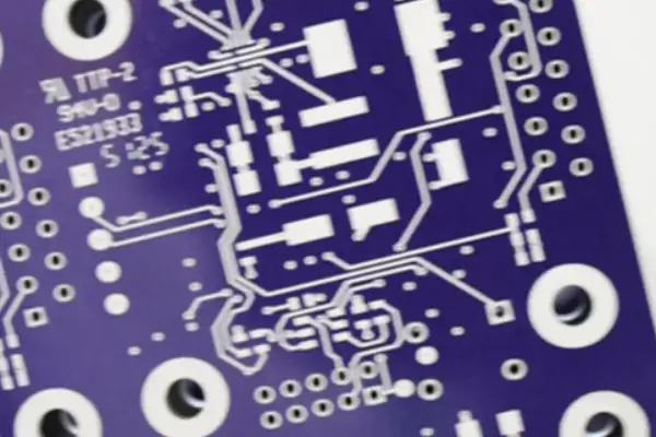
Isolation Architecture: The Physical Foundation of System Reliability
A recurring design error in medical imaging boards: assuming that optical coupler isolation in the schematic is sufficient isolation on the board. The PCB’s physical layout is the actual test. High-voltage side interference will find paths across through ground plane coupling, through power layer noise crosstalk, through routes the designer did not anticipate.
One board test found that the functional prototype operated correctly, then readings started drifting in a field environment. Extended investigation revealed the root cause in a multilayer PCB supplier’s process: they had cut corners on the isolation band treatment in inner layers, failing to implement complete physical separation in all signal layers. High-voltage zone noise then affected the low-voltage metering circuit’s reference source. This type of problem is invisible on drawings. It only surfaces under actual hardware in high-temperature, high-humidity environments.
The correct rule: physical isolation must be complete and consistent across every layer. The isolation boundary cannot exist only on surface layers while conductors cross at the same location in inner layers. Physical isolation slots cut through the PCB substrate between high-voltage and low-voltage conductor regions provide protection that surface distance alone cannot reliably maintain over years of clinical use.
HDI PCB Manufacturing Requirements for Medical Applications
Contemporary high-performance SoCs use package pitches below 0.4 mm. Standard through-hole vias cannot achieve the routing density this requires. Blind and buried via structures — the defining technology of HDI — enable the necessary interconnect density.
Laser drilling parameters, plating bath chemistry, fill uniformity, and registration tolerance all contribute to via quality. A via that appears within specification in cross-section samples but has structural inconsistency at the microscopic level may pass incoming inspection and fail after thermal cycling. Copper plating thickness variation along the via barrel changes its thermal and electrical resistance characteristics under temperature variation.
A capable HDI PCB manufacturer for medical applications can discuss these parameters directly: how laser drilling stability is monitored across a production run, what characterization data shows for plating uniformity across different panel positions, how residual stress in filled via structures is managed. These answers reveal whether the supplier’s quality system is built on actual process understanding or on documentation.
Mixed-Signal Layout Discipline
The instinct to pursue extreme integration density — placing all functions onto one highly integrated control board — creates predictable electromagnetic compatibility hazards. A board the size of a palm simultaneously running high-speed digital signals, analog sensor measurement circuits, and RF communication modules is an EMC engineering challenge of the first order. Harmonic noise from digital circuit switching couples readily into sensitive analog receive paths.
The analog measurement circuit layout is one of the most consequential and least discussed aspects of Medical Imaging PCB design. The accuracy of the voltage and current measurements depends entirely on the quality of the signal path from sensor to converter. Star-topology grounding — routing each sensitive measurement circuit’s analog reference connection to a single common point rather than sharing a ground conductor with other circuits — minimizes the error contributed by ground potential differences between measurement points.
One practical example: a portable ultrasound device project with an extremely compact initial design produced persistent background noise points that could not be eliminated. The critical analog acquisition section was subsequently built on a separate subboard and connected to the main board through a carefully designed connector and shielding layer. The problem was resolved. That project crystallized a principle: for medical PCBs, reliability always ranks first, and reliability’s foundation comes from respecting physical laws and understanding the nature of signals. Software algorithms cannot fully correct for hardware design deficiencies introduced at the design stage, especially when those deficiencies affect the purity of the images that physicians use for diagnosis.
Material Selection and Long-Term Clinical Exposure
Hospital environments impose sustained chemical stress that standard industrial environments do not. Various disinfectants, alcohol, and patient-contact fluids are all potential attack vectors. A qualified medical device PCB requires chemical corrosion resistance consideration beginning from substrate material selection, careful plating process control to avoid heavy metal ion leaching risks, and deliberate surface treatment selection.
ENIG is widely used in the medical field for the stable, chemically inert barrier its thin gold layer provides. Gold resists oxidation and reaction with disinfectants, protecting underlying nickel and copper layers. The quality of the nickel layer beneath the gold — specifically, the “black pad” failure mode associated with process chemistry inconsistencies — requires specific quality controls at the manufacturing stage, not just incoming inspection of the finished surface.
Sterilization method compatibility is a dimension most designers overlook. Ethylene oxide gas sterilization may react with certain conformal coating components. High-temperature steam sterilization tests base material heat resistance and whether solder joints crack from thermal expansion cycling. Gamma radiation sterilization has different material compatibility requirements. Each sterilization approach demands specific material and coating selection — one default choice does not serve all sterilization environments.
Biocompatibility testing requirements extend beyond direct patient-contact components. The solder mask inks and cleaning agent residues on a PCB may release trace substances that accumulate inside a sealed enclosure over time, affecting device stability or safety. This is not a theoretical concern — it is a recognized failure mode in long-service-life medical equipment.
ISO 13485 as Engineering Culture
ISO 13485 certification is frequently cited as a quality indicator. Its value depends entirely on whether the organization treats the standard’s requirements as engineering discipline or as documentation exercise.
Evidence-based decision culture permeates organizations where ISO 13485 is genuinely embedded. When an engineer raises a question about whether a capacitor’s temperature behavior might affect measurement accuracy, a compliance-oriented organization produces a document confirming the specification was met. An engineering-oriented organization runs the experiment, records the result, and adds the measurement as a verification item.
Full traceability — linking every component in every shipped unit to its procurement lot, production batch, test data, and assembly parameters — is not primarily a compliance requirement. It is an engineering tool. When a field failure occurs, traceability enables systematic investigation: were other units using the same component lot affected? Did the failure correlate with a specific production shift’s oven profile? Without this data, field failure investigation is anecdotal.
One instructive case: a batch of boards that passed all IPC standards in incoming inspection showed performance degradation in one filter capacitor after extended accelerated aging tests — not complete failure, but deviation from initial values unacceptable for a high-precision control system. Analysis revealed that the capacitor’s procurement specification, while meeting industry general standards, had no special requirements for long-term performance under sustained voltage stress. The resolution was collaborative specification revision with the supplier, adding more stringent long-term reliability test conditions to the procurement agreement.
Doing medical electronics requires not just meeting standards — it requires understanding what risks each standard exists to prevent, then thinking about how to exceed that standard for the specific product.
Supply Chain and Long-Term Reliability Perspective
Selecting an HDI PCB supplier for medical imaging applications requires evaluating not only process capability but supply chain stability and organizational quality culture.
Every component on a board has a batch number. Soldering temperature profiles, test data at every measurement point — all must be linked to a specific board. Every person in the chain, from materials handlers to test engineers, must share a common understanding: they are not building an ordinary circuit board. Any link’s carelessness or omission breaks the traceability chain, making root-cause investigation after a field failure nearly impossible.
Some boards in a long-running hospital installation showed performance degradation after years of service — subtle delamination had developed in the multilayer PCB, damaging signal integrity. This type of problem is extremely difficult to detect in short-term laboratory testing. It emerges only after months or years of continuous operation, as cyclic temperature and humidity changes gradually degrade the bond between substrate and copper foil.
The boards in a medical imaging system will carry current, manage signal acquisition, and enable diagnostic imaging for the duration of the product’s service life. They will not be accessible for routine inspection. Problems that develop slowly over years become visible only when they have progressed far enough to affect system performance. The investment in getting the design right, the material selection right, and the manufacturing partner right pays back over the entire service period.
For a product where every design decision carries the weight of a patient’s health and safety, the attitude of checking every detail repeatedly until the most reliable answer is found must pervade the entire development and production process. Every detail, from power path current-carrying capacity to solder joint failure mode analysis to test procedure clarity — all of it matters, because there are no second chances.
Failure analysis on an Industrial Vision System PCB rarely reveals what it
What actually makes a long-term PCB supply chain partnership work — shared
Practical, experience-based strategies for how to reduce PCB procurement risks — from
- Эксперт в области мелко- и среднесерийного производства
- Высокоточное изготовление печатных плат и автоматизированная сборка
- Надежный партнер для электронных проектов OEM/ODM
Часы работы: (пн-сб) с 9:00 до 18:30
Get quote, solution or any question, Andre always here to help