

Who Should Build Your CT Scanner PCB? I Have Hit More Pitfalls Than the Board Has Layers
Choosing a CT Scanner PCB manufacturer? Real lessons on detector boards, slip
People tend to overcomplicate what makes a smart energy meter actually “smart.” The headline features — remote monitoring, app-based consumption analysis, time-of-use pricing visibility — are genuinely useful. But the most fundamental value that an electricity meter delivers has not changed since the mechanical dial era: the number it shows must be accurate, and it must stay accurate. That simple promise, sustained through twenty years of installation in a metal cabinet on an exterior wall, is where the engineering challenge actually lives.
Engineers who work on smart meter PCB design describe the core problem not as feature implementation but as honesty under duress. Can this board deliver a correct reading at minus fifteen degrees in a northern winter? Can it do the same thing at seventy-five degrees inside an outdoor meter enclosure on a summer afternoon, with voltage sag on the line and a switching power supply nearby generating broadband noise? The meter that passes these tests without drifting is the one that earns trust.
Visiting a housing renovation project made this concrete. New single-phase meters installed alongside legacy equipment in cramped enclosures face a thermal environment that would accelerate aging in almost any board. The hardware supporting those readings — material selection, process controls, long-term aging validation — is unglamorous work done quietly and mostly invisibly. But it is the work that determines whether the meter that counts energy for the next twenty years counts it correctly.
The conversation about multilayer PCB manufacturing for energy meters often fixates on layer count. This misses the point. A well-planned four-layer or six-layer board will outperform a carelessly designed eight-layer board on every metric that actually matters for metering applications: signal integrity, EMC suppression, and long-term stability.
A standard four-layer structure — top signal layer, power plane, ground plane, bottom signal layer — with uninterrupted power and ground reference planes provides a solid foundation for mixed-signal metering applications. The ground plane provides a continuous low-impedance reference for every analog sampling circuit on the board. The power plane reduces supply distribution impedance, which limits the voltage variation that switching logic generates in the rail supplying the analog front end. These functional benefits come from how the layers are allocated, not from adding more of them.
The precision resistor networks used for voltage and current sampling deserve more attention than they typically receive. A resistor network specified at one percent tolerance may show significant variation in temperature coefficient between batches from the same manufacturer, leading to slow reading offset after years of installation in a thermally variable environment. Testing different batches — not just against initial specification but over a temperature sweep — reveals the long-term behavior that determines whether a factory-calibrated meter stays accurate three years later.
The distinction between a manufacturer capable of making complex boards and one capable of making boards that perform reliably for two decades under metering conditions is found in different questions. Do they control and characterize incoming substrate materials on a lot-by-lot basis? Do they maintain production environment temperature and humidity within defined limits and document deviations? These process controls are invisible in the finished board but determine whether the finished board performs as designed for the full service life.
One design failure that appears repeatedly in early smart meter products is the consequence of inadequate isolation between high-voltage sections and low-voltage digital circuits. A single-phase meter must handle the 220V AC grid signal while simultaneously providing a clean low-voltage operating environment for a microprocessor and RF communication module. That coexistence, on a board the size of a palm, requires deliberate physical isolation architecture.
An engineer who learned this problem firsthand described using a conventional two-layer design for cost control in an early product. Within six months of field deployment in a humid environment, leakage current between inadequately separated high-voltage and low-voltage domains caused a near-safety event. The redesign upgraded to a four-layer board with dedicated isolation geometry between the two voltage domains. The result was measurably improved stability and approximately fifteen percent lower standby power consumption — the latter attributable to reduced spurious coupling losses in the more systematically routed layout.
The physical isolation requires more than separating traces by a distance calculated to the minimum standard. Humidity, dust accumulation, and time all reduce the effective creepage distance on a board surface relative to the clean-air design calculation. Manufacturing the isolation with physical slots cut through the board substrate between high-voltage and low-voltage domains provides protection that surface distance alone cannot reliably sustain over a twenty-year service life in outdoor or semi-outdoor installations.
The metering chip itself is the least likely point of failure in a well-sourced smart meter design. The mainstream chip families are mature, well-characterized, and capable of meeting national metering standards. Where designs diverge in long-term accuracy is in the external circuit — the sampling network, the reference source, the power supply filtering — and in the layout that connects them.
Decoupling capacitor placement for the LDO regulators supplying the MCU and analog front-end chip matters more than the capacitor selection itself. A capacitor placed centimeters from the supply pin it is meant to decouple does very little useful work at the frequencies where switching noise is generated. The same capacitor placed immediately adjacent to the pin provides the local charge reservoir that absorbs switching transients before they appear on the supply rail.
Analog ground and digital ground connection topology determines whether digital switching current flows through the analog measurement reference. The single-point connection between these ground domains is most effective when located at or near the ADC — the component most sensitive to reference contamination. Digital return currents following this path flow away from the analog sampling circuits rather than through them.
A practical case illustrated what happens when these disciplines are violated: a board carrying both a PLC power-line communication module and a narrow-band wireless module experienced mutual interference so severe during integration testing that neither module could operate correctly. The resolution required replanning the board stackup to add a complete shielding ground plane between the two communication sections, physically separating their RF front ends on opposite corners of the board, using independent LDO regulators for each with dedicated input filtering, and routing the clock signal away from frequencies that fell within the wireless module’s receive band. Each step individually addressed part of the problem; all were required together.
Modern smart meters integrate one or more communication interfaces — PLC carrier, NB-IoT, 4G LTE, LoRa, or similar — alongside the core metering function. Each wireless interface introduces an RF front end that must coexist with the digital processing and the analog sampling circuits on the same board.
The wireless module’s burst transmissions generate transient current demands that appear on its supply rail and, if the supply is shared without adequate filtering, on the rails serving other circuits. A meter that reads correctly under steady-state conditions may show reading errors precisely at the moments when a communication burst occurs — a correlation that is difficult to identify without systematic investigation because the timing relationship is not visually obvious.
High-quality isolation between communication modules and metering circuits typically requires separate regulation for each domain, physical separation of antenna structures from high-current sampling circuits, and careful management of return current paths to prevent RF ground currents from flowing through the analog measurement reference.
A potential future architecture worth considering is functional modular design: a core metering board handling the precision measurement function, with communication modules implemented as pluggable subboards connected through defined interfaces. This approach avoids the need to redesign the entire board when communication technology changes, simplifies fault diagnosis by isolating functional domains, and allows communication module certification to proceed independently of metering module recertification. The architecture imposes PCB design requirements of its own — high-speed board-to-board connector selection, impedance matching at interfaces, and mechanical tolerance management — but these are knowable problems with established engineering solutions.
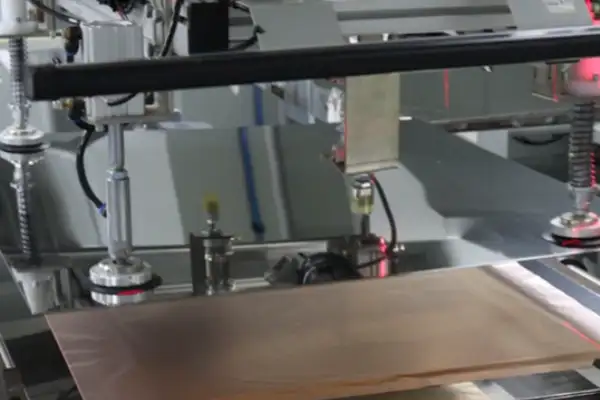
A fabrication quality comparison between two meter PCB manufacturers at the same design specification revealed performance differences that were invisible in the design files but visible in the finished boards. The manufacturer using a high-automation production line with in-process statistical control produced boards with full solder joint wetting, dimensionally consistent trace edges, and smooth, uniform surface coating. The manufacturer using primarily manual operations with less disciplined quality inspection produced boards with detectable cosmetic defects and, more significantly, measured variation in solder joint quality that correlated with observed field reliability differences.
The lesson: the quality of a complex PCB is largely determined before the design files arrive at the factory. It is determined by whether the factory maintains process controls that produce consistent results day after day, shift after shift, batch after batch. Certification documents can attest to process existence; production data tracks demonstrate process consistency. The second is the more reliable indicator.
Moisture protection during the manufacturing process matters particularly for boards that will spend decades in outdoor or semi-outdoor installation. Flux residue that is incompletely removed during the cleaning step provides a hygroscopic surface that accelerates corrosion under humid conditions. Conformal coating applied over inadequately cleaned boards can trap moisture rather than excluding it. The soldering process details — flux activity level, cleaning chemistry, post-clean inspection — determine the board’s starting condition for its long service life.
For smart energy meter boards specifically, the soldering approach for large through-hole components — transformers, relays, heavy terminal blocks — deserves deliberate engineering attention. These components are not ideally served by the same reflow process used for precision SMT components. Wave soldering or selective soldering matched to these components’ mechanical and thermal characteristics produces more consistently reliable joints than forcing all components through a single process profile optimized for neither.
The most useful question when evaluating a multilayer PCB manufacturer for smart meter work is not about their highest layer count or their finest achievable line width. It is: walk me through a problem you identified in production in the last year and what process change resulted. The answer reveals whether the organization learns from its production data or only reports it.
Choosing a CT Scanner PCB manufacturer? Real lessons on detector boards, slip
Body-worn camera performance often depends on the PCB. Learn how HDI stackups,
A colleague’s ultrasonic parking sensor PCB was ruined by a cheap board:
- 중소규모 배치 생산 전문가
- 고정밀 PCB 제작 및 자동화된 조립
- OEM/ODM 전자 프로젝트를 위한 신뢰할 수 있는 파트너
영업 시간: (월~토) 9:00~18:30
Get quote, solution or any question, Andre always here to help