
From Novice to Expert: Sharing My Experience in Pin Header PCB Selection
As an electronics enthusiast, I’ve come to understand firsthand the impact of
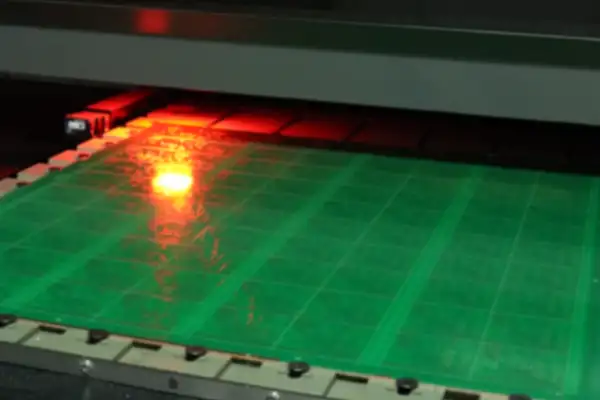
I recently witnessed a new Connector PCB Terminal Blocks installation process in a factory and discovered that engineers now have much more complex requirements for these small components than I imagined.
I remember five years ago, the terminal blocks we used were basically just about tightening screws to make it work. Now it’s different; just selecting the right model requires considering a whole host of factors. Last time, a project had to be reworked because the wrong model was chosen.
I think the most troublesome are those models with extremely small spacing. For example, some products claiming to be miniaturized have spacing as small as millimeters, requiring extra care during installation. I once witnessed a technician short-circuit two adjacent contacts because his hand trembled during installation.
However, today’s terminal blocks are indeed much more reliable than before. The most extreme case I’ve seen is a device that ran in a humid environment for three years, and when opened, the terminals inside showed no signs of rust. This would have caused problems on older models long ago.
Speaking of installation methods, I think the currently popular push-in design is indeed much more convenient. But some people, to save time, just shove the wire ends in without even cleaning them, which I strongly disagree with.
Another thing that impressed me was that last year, our factory purchased a batch of terminal blocks, and the supplier provided complete material traceability information. This was unimaginable in the past, considering it’s just a small part.
I increasingly feel that choosing the right terminal block is crucial. Sometimes, when equipment malfunctions, the problem turns out to be with these seemingly insignificant connectors.
Especially in applications requiring high current handling, selection must be extremely careful. I remember once using a terminal block with a nominal mm pitch during testing, and the entire connector warped due to overheating.
Ultimately, while these connectors may seem simple, their proper use relies heavily on experience. Now, I consider the actual operating conditions more meticulously when selecting components; after all, I’ve learned the importance of caution from past mistakes.
Every time I see a well-designed circuit board, I can’t help but take a closer look, especially at the interface between the connector and the PCB—sometimes a seemingly insignificant detail can determine the entire product’s lifespan. I’ve encountered numerous failures caused by improperly selected connector PCB terminal blocks, many of which stemmed from the performance of the insulation materials.
Surface treatment is often underestimated. I remember once debugging outdoor equipment where all electrical clearances met standard specifications, yet abnormal discharge occurred during consecutive rainy days. It was later discovered that dust and moisture on the terminal block surface had created a conductive path. This situation was particularly troublesome because the problem wasn’t with the copper foil spacing.
This is where the importance of the CTI (Content Tolerance Index) comes in. I tend to view the CTI value as a material’s “resilience index” against surface leakage. A higher value means the material maintains insulation better in humid and polluted environments. In one comparative test, we tested two different terminal blocks: in a salt spray test simulating high humidity, the low-CTI material quickly showed carbonization marks on its surface, while the high-CTI version maintained good insulation performance.
Many people overlook the actual operating conditions after terminal installation when laying out PCBs. I once participated in improving an industrial controller project. The initial design only considered safe spacing under static conditions, but in actual use, temperature changes inside the device caused condensation. We added an isolation groove structure between adjacent terminals, which effectively blocked leakage paths even if contaminants accumulated on the surface.
When selecting connectors, in addition to current and voltage parameters, material properties should be given more attention. Once, after changing suppliers, the equipment suddenly experienced intermittent malfunctions. Later investigation revealed that the new supplier was using plastic materials with a CTI value two levels lower than the original specifications. This lesson taught me that sometimes unseen parameters are more important than explicit specifications.
In practical applications, I prefer a multi-layered protection approach. For example, in high-voltage areas, I not only ensure sufficient electrical clearances but also select terminal blocks with special surface treatments, and even apply a moisture-proof coating to the PCB when necessary. This combined strategy is often more reliable than simply increasing safety clearances.
Recently, while tidying up my studio, I found a bunch of old connector PCB terminal block accessory boxes. These things look insignificant but are quite interesting. I used to think wiring was just about stuffing wires in and tightening them, but I later discovered there’s more to it than meets the eye.
I remember once helping a friend repair an old amplifier and suffering from problems caused by the terminal blocks. Opening the chassis and seeing the densely packed wiring harness, I was quite confident, thinking it was just a matter of replacing a part. But after much troubleshooting, I discovered that the problem was a faulty clamping force on a certain terminal, causing poor contact. That location, right next to the heatsink, had caused the wires to loosen due to constant thermal expansion and contraction. The most frustrating thing was that this problem was intermittent; sometimes a couple of taps would fix the machine, leading people to mistakenly believe the problem lay elsewhere.
Many people think only industrial-grade connectors require such attention to detail, but similar issues exist in household appliances. For example, the terminal blocks at the motor wiring connection in a washing machine are constantly exposed to vibration; if the clamping structure isn’t designed properly, they can easily loosen. The most extreme example I’ve seen is a dryer’s heating module where poor wire contact caused localized overheating, warping the plastic casing.
Now, when selecting components, I pay special attention to the details of the clamping structure. Some cheap products look like they have thick copper plates, but the spring design is fundamentally flawed. They might work fine initially, but their problems become apparent over time. Good terminal blocks should be compatible with different wire diameters, as mixed wire thicknesses are frequently encountered in actual wiring.
Recently, when remodeling the studio’s lighting system, I specifically chose a rewiring-compatible model. Although the unit price is higher, maintenance is much easier. Once, adjusting the circuit layout allowed for simple plug-and-play rewiring, saving the hassle of cutting and reconnecting wires. This design is a boon for those who frequently tinker with equipment, ensuring both reliability and flexibility.
In fact, connector selection often reveals a person’s work style. Some pursue extreme tightness, screwing every screw down to the limit, which actually accelerates metal fatigue. Truly reliable connections should allow for appropriate elasticity in the material while ensuring good contact; after all, thermal expansion and contraction are physical laws that no one can escape.
Having seen too many cases of failure due to small details, I now prefer to pay more attention to these basic connectors. After all, even the most complex systems ultimately function through these seemingly simple nodes, and often the root of the problem lies hidden in these inconspicuous interfaces.
I’ve seen too many malfunctions in the factory caused by improper terminal selection. Once, equipment inexplicably stopped, and after a long investigation, it was found that the contacts on the connector PCB terminal blocks were burnt out. The workers habitually plugged and unplugged the wires a few times and that was it, completely ignoring the compatibility between the cable and the terminal. This seemingly simple operation hides a lot of intricacies.
Many people only focus on the current parameters when choosing terminal blocks, which is actually quite dangerous. The same nominal current can behave drastically under different ambient temperatures. I once handled a piece of equipment that kept tripping in the summer, and it turned out that the temperature rise was not calculated correctly—the internal temperature of the control cabinet where the terminals were located could reach 60 degrees Celsius. At this temperature, the rated current needs to be reduced by 30% for safety. Nowadays, designs intentionally leave room for heat dissipation, for example, placing high-current terminals near ventilation openings.
Loose terminals in vibration environments are even more troublesome. Once, a control cabinet installed next to an assembly line developed intermittent signal after only three months of use. It was later found that the holding force of the spring-loaded terminals was insufficient. Now, in vibration-prone environments, I’d rather spend 30% more to choose a model with a locking mechanism, since the labor cost of replacing terminals is much higher than the cost of the parts themselves.
Frequent plugging and unplugging requires even more special consideration. In the lab, those test interfaces that are connected and disconnected dozens of times a day, ordinary screw terminals would loosen after six months. Replacing them with spring-loaded, self-locking plug-in terminals has kept them problem-free for three years. Although the unit price is higher, the saved maintenance time is far more valuable.
Recently, while helping a friend upgrade old equipment, I discovered an interesting phenomenon: terminal blocks of the same specifications, European and domestic brands differ in structure. For example, for terminals rated at 25A, European products often use thicker copper material with heat sink fins, while some cheaper products, although having similar initial conductivity, heat up significantly faster under sustained load. This reminds us that we can’t just look at the specifications; we must also consider the specific application scenario.
In fact, choosing a terminal block is like duplicating a key—it’s not just about whether it fits; long-term stability must also be considered. Sometimes, more screw fixing points or more ventilation holes can extend the life of the equipment by several years. These details are often more important than pursuing ultra-high specifications.
I’ve always found connector PCB terminal blocks quite interesting. Many people only look at whether the current parameters are sufficient when choosing terminal blocks. In fact, what truly affects lifespan are often the easily overlooked details.
I remember once disassembling and repairing old equipment and discovering a phenomenon: after three years, the same circuit board layout using terminal blocks of different materials showed a significant difference. Some brands’ plastic casings had become brittle and cracked, while others only showed slight discoloration. Later, I realized this was related to the cumulative temperature rise during daily operation.
Resistance changes are a very subtle process. Sometimes, a multimeter shows good continuity, but the actual contact points may have already formed an oxide layer. This is especially noticeable in applications with frequent high current fluctuations; for example, in motor control circuits, the terminal block temperature can be observed to be significantly higher than surrounding components.
Now, when designing circuits, we deliberately leave sufficient heat dissipation space around the terminal blocks, even if it takes up more PCB area. After all, accumulated heat not only affects connection reliability but can also affect the stability of the entire board.
During a test, I discovered an interesting phenomenon: wires of the same cross-sectional area connected to terminals with different plating thicknesses could have a temperature difference of seven or eight degrees Celsius after prolonged operation. This made me start paying attention to details beyond contact resistance. For example, the heat dissipation design of the crimp structure is actually more important than simply pursuing low resistance.
Many connection problems are slow processes that don’t immediately appear but become increasingly apparent over time. When selecting terminal blocks, in addition to looking at the rated parameters, it’s crucial to consider the temperature fluctuations in actual applications, since the equipment is meant to operate long-term, not just for a short test.
I’m used to adding extra temperature monitoring points on critical circuits and observing the temperature rise curve through data recording. This approach is more intuitive and better reflects the changes in state under real operating conditions than simply relying on theoretical calculations.
Ultimately, these connecting components, though seemingly insignificant, directly affect the stable operation of the entire system. Sometimes, paying a little more attention to details can prevent many problems later on.
I’ve seen too many equipment failures caused by wiring problems. Sometimes it’s just a small screw that wasn’t tightened properly.
Once, I saw a piece of equipment inexplicably stop working on-site. Upon disassembly, I found that the wiring on the connector PCB terminal blocks was loose. The worker said he tightened it, but in reality, the required torque value wasn’t reached. This half-tight state is the most dangerous. It might work normally at first, but problems will occur over time. Many people think that tightening screws is as simple as just a couple of turns. However, different types of terminals have completely different torque requirements. Too tight, and the threads are easily damaged; too loose, and the contact resistance increases, leading to increased heat.
I remember once testing with a torque wrench, adjusting each connection individually, and finding that achieving the standard torque could reduce the temperature rise by more than ten degrees Celsius. This is not a small number; over the long term, it significantly impacts the lifespan of the equipment.
Soldering points on PCBs are also a potential hazard. Especially with terminals that have pluggable/pluggable functions, repeated plugging and unplugging can easily cause micro-cracks in the solder joints. This damage is cumulative; initially, the resistance measurements may be normal, but by the time problems are discovered, large-scale rework is often required.
Now, when designing circuit boards, I deliberately make the terminal area more robust. For example, I increase the pad area and add mounting holes. Although the cost is slightly higher, it’s far more worthwhile than the hassle of later repairs.
The worst situation is when multiple strands of wire are directly stuffed into the terminal. It looks connected, but only a few copper wires are actually conducting electricity. Over time, oxidation and heat problems arise. That’s when you realize how important it is to use a suitable cold-pressed terminal. Good connector design should make installation simple and intuitive. For example, a terminal with a locking mechanism provides a clear tactile feedback when fully inserted, preventing mis-insertion and avoiding many basic errors.
Ultimately, electrical connections are a highly technical skill that allows no room for carelessness. It’s always a pity to see equipment burn out due to wiring problems; it could have been avoided with a little more attention.
Have you encountered similar situations?
I’ve been soldering for many years. In the beginning, I always thought that piling up a thick layer of solder would guarantee a strong connection—but guess what? Those seemingly full solder joints were actually the most prone to problems. Later, I realized the key is whether the solder can truly penetrate into the metal gaps to form an alloy layer.
Connector PCB terminal blocks with plastic shells are particularly demanding in terms of craftsmanship. Plastic heats up slowly but dissipates quickly, easily causing cold solder joints. I’ve seen too many cases where the surface looks shiny and smooth, but the internal bonding is completely poor; a slight pull and the entire terminal falls off.
The threat of humid environments to circuit boards is more insidious than imagined. Last year, while inspecting an outdoor device, I discovered that the terminal blocks were covered with a fine layer of verdigris. Salt and moisture in the air mixed with the moisture created tiny conductive paths between the terminals. Although it wasn’t a short circuit, the insulation resistance had dropped to a dangerous level.
The CTI (Conductivity Tolerance) rating of materials is often underestimated. In one test, terminal blocks from different manufacturers showed carbonization marks on their surfaces under the same contamination conditions, while materials with high CTI values maintained surface insulation even when covered in dust. This difference is like the difference between a non-slip tire and a regular tire on mud.
Conductivity isn’t just about the metal itself. I once encountered a faulty terminal where the copper material itself was of good quality, but because the plating was too thin, it oxidized quickly in a humid environment, becoming a resistive point. This reminded me that when evaluating connectors, I need to consider the overall design, not just a single parameter.
The most easily overlooked issue is the accumulation of contaminants during routine maintenance. One machine was cleaned with compressed air every year during maintenance, but the high-pressure airflow actually blew oil into the terminal gaps. Over time, these contaminants absorbed moisture and became potential leakage paths.
Many problems stem from assumptions, such as believing that heavy-duty connectors are necessary for industrial environments while ignoring specific operating conditions. Sometimes, a simple dust cover is more effective than a complex sealing structure—this is something experience has taught me.
I’ve seen far too many machines returned for repair due to problems with connector PCB terminal blocks. Many people think soldering is simply connecting wires, but it’s far more complex than you imagine.
Soldering quality largely determines the reliability of the entire connection. Sometimes solder joints appear full and shiny, but breakage occurs during actual use. This is often due to improper temperature control during soldering or flux residue causing embrittlement.
The choice of terminal blocks is also crucial. Some engineers choose cheap terminal blocks to save costs, resulting in loose pins and complete connection failure under high-frequency vibration. One of my clients had a production line shut down for two days because of this, incurring losses far exceeding the cost of the materials saved.
Many people overlook a crucial detail: the difference in expansion coefficients between different materials can pose hidden dangers. Especially in industrial environments with large temperature differences, the thermal expansion and contraction of metals can create continuous stress at the solder joints. Over time, this can lead to micro-cracks. Initially, it might be an occasional malfunction, but by the time it completely breaks down, it often has serious consequences.
Mechanical stress is also a hidden killer. During one maintenance inspection, it was discovered that insufficient slack in the wiring allowed even slight vibrations from equipment operation to be transmitted through the cables to the solder joints. This continuous, minute vibration eventually led to fatigue fracture of the solder joint.
Preventing these problems isn’t difficult. Thorough surface cleaning before soldering, controlling the soldering temperature and time, choosing reliable terminal blocks, allowing adequate buffer slack in the wiring, and regularly checking the condition of the connection points—these seemingly simple steps can help you avoid many unnecessary troubles.
I believe that rather than trying to fix problems after they occur, it’s better to pay attention to these details from the beginning. After all, a stable connection is the foundation for the normal operation of equipment; if this foundation is weak, even the best design can be rendered useless.
Sometimes, the most basic steps are the most challenging, and the use of connector PCB terminal blocks is a prime example.
I remember last year, when I was helping a friend renovate their basement lighting system, I realized the importance of connector PCB terminal blocks. To save time, I bought the cheapest terminal blocks and installed them. Two months later, the entire circuit started tripping frequently. When I disassembled them, I found that the plastic casings of those cheap terminals had developed micro-cracks, and the internal metal contacts had oxidized and turned black.
That experience taught me that in the field of electrical connections, you can’t just look at the price tag. Especially in high-humidity environments, material selection is often more critical than we imagine. Some terminal blocks on the market that claim to be durable actually use recycled plastic, which easily deforms when exposed to moisture, let alone has long-term stability.
Later, I switched to connector PCB terminal blocks made of polyester, and the results were completely different. This material is not only moisture-resistant but also withstands greater temperature fluctuations. Once, I used a thermal imager to check and found that even under full load, the temperature of the terminals was significantly lower than that of the surrounding components, indicating that the contact resistance was indeed well controlled.
In fact, many people easily overlook the importance of accessories. For example, small things like marking strips can help you quickly locate problems in complex wiring, while suitable terminal blocks can prevent cables from being accidentally pulled. These details may seem insignificant, but they can save a lot of troubleshooting time in actual maintenance.
Regarding installation methods, I personally prefer spring-loaded connections. Although they require special tools for crimping, there’s generally no need to worry about loosening after installation. In contrast, screw terminals, if the torque isn’t controlled properly, can either result in poor contact or damage to the wires, increasing the risk of failure.
Recently, I’ve noticed that some new Connector PCB Terminal Blocks are starting to integrate digital identification functions. By scanning a QR code, you can obtain complete parameter information. This design is particularly user-friendly for later maintenance. However, at this stage, I’m more focused on basic performance; after all, even the most intelligent features can’t compare to a reliable physical connection.
In the future, I might try more modular wiring solutions, but the Connector PCB Terminal Blocks I’m using now already meet all my requirements for stability. Ultimately, the core of electrical connections is safety and reliability; other fancy features are just icing on the cake.
Every time I see disassembly diagrams of devices where connectors malfunction due to vibration, I wonder—have we complicated simple things? I recently encountered a similar situation while repairing an old industrial controller for a friend. Upon opening the casing, I saw that several connector PCB terminal blocks had developed micro-cracks in their solder joints. Although not completely broken, they clearly wouldn’t last much longer.
This kind of problem is actually quite common. Many people’s first reaction is to increase the soldering pressure or replace the terminal blocks with more expensive ones. But I think the key isn’t the soldering itself, but whether we’ve given these connection points enough breathing space. Imagine you’ve directly plugged a heavy cable into a terminal block, with the other end dangling in the air. Over time, even the strongest solder joints won’t withstand this continuous pulling. Those tiny vibrations will be amplified by the terminal block housing like a lever, ultimately pressing down on the fragile solder joints.
I prefer to leave a little slack in the wiring, allowing the cable to have a natural bend rather than being taut. This way, even if the equipment vibrates during operation, or someone accidentally bumps into the cable, the force will be absorbed by this bend before being directly transmitted to the solder joints. Sometimes, a simple change is more effective than replacing materials.
Regarding soldering methods, I’ve found that through-hole mounting is indeed much more reliable than surface mount, especially in applications requiring mechanical stress. Through-hole leads passing through the entire PCB are like deeper steel reinforcement in a foundation, naturally providing greater stability. However, even with through-hole soldering, problems can still occur if the solder doesn’t completely fill the holes or if cold solder joints exist.
Once, while inspecting a piece of equipment, I found that its connector PCB terminal blocks, although using a through-hole design, had noticeably uneven solder joints, with some areas even showing gaps. In such cases, under external force, stress concentrates on those weak points, often leading to cracks. Good soldering should completely envelop the entire pin, like a full drop of water, not a patchy mess.
I believe that the design phase should consider the actual usage scenario, not just the specifications. For example, this controller, intended for a vibration environment, had its terminal blocks mounted directly on the PCB edge without any auxiliary support. Later, I added a simple bracket to secure the cables, and the problem disappeared. Sometimes, the solution doesn’t need to be sophisticated; the key is addressing the root cause of the problem.
Another easily overlooked point is the difference in thermal expansion coefficients between different materials. The materials of the PCB board and the terminal block expand at different rates when heated. If insufficient margin is left in the design, temperature changes themselves will create additional stress on the solder joints. Especially in industrial environments with large temperature differences, this accumulated thermal fatigue can be more fatal than a sudden external force.
In fact, many connection problems are not caused by a single factor, but are the result of various small details accumulating. Like building blocks, even a slight mismatch between individual blocks will make the overall structure unstable. Rather than fixing problems after they occur, it’s better to think ahead about the actual usage scenarios from the beginning and prepare accordingly.
Ultimately, reliability doesn’t depend on the exceptional strength of a single component, but on the coordinated operation of the entire system. A good connector PCB terminal block design should consider not only electrical connections but also mechanical protection, thermal management, and ease of daily maintenance. By considering every step, the final product will naturally withstand the test of time.
Every time I disassemble equipment and see those densely packed terminals, I think about this question: Why do we always focus on superficial phenomena like whether the screws are loose or the springs are strong enough? The real factors affecting connection reliability are often overlooked, fundamental operational details.
Last week, while repairing an old audio device for a friend, I encountered this situation. Upon opening the junction box, I found it used connector PCB terminal blocks with metal springs. This design should theoretically be very stable, but one channel consistently produced static. Further investigation revealed that while the previous repairman had inserted the wires properly, several copper wires were sticking out and not fully pressed into the clamping area. As a result, these thin wires would occasionally touch the adjacent grounding terminal. This subtle poor contact caused intermittent signal interruptions.
Many people believe that a click indicates the wire is properly inserted, but this is not always the case. Especially with thin, multi-strand wires, the cores are prone to unraveling. If you don’t gently twist them before inserting, some strands may be blocked outside the contact point. In this case, even with strong spring pressure, only a few thin wires, not the entire cross-section, will conduct electricity.
Another easily overlooked issue is terminal cleaning. Once, while debugging equipment in a high-humidity workshop, despite checking all wiring, a certain sensor signal kept fluctuating. It turned out that a thin layer of oil had accumulated inside the terminal. Although the screws were tightened tightly, the dirt inside increased the actual contact resistance. This problem cannot be solved simply by tightening; a thorough cleaning of the contact surface is necessary.
I think that instead of agonizing over whether to choose a screw or spring structure, it’s better to cultivate good wiring habits. For example, the wire stripping length should be exactly matched to the terminal depth; multi-strand wires should be pre-twisted into a single strand, and after insertion, gently pull back to test for a secure fit. These seemingly simple actions are often more important than the differences in the components themselves. After all, even the best design cannot withstand careless handling.
I’ve seen too many engineers treat the terminal blocks on the PCB as the simplest components. “It’s just a wiring place, right? Just tighten the screws, isn’t that enough?” This kind of thinking is precisely what creates hidden dangers. In fact, these small connection points are often the most vulnerable parts of the entire system.
I remember encountering a strange phenomenon last year when debugging a piece of equipment: after the machine had been running for half an hour, the signal of a certain sensor became unstable. After checking for a long time and finding no problems with the program or broken circuitry, it was finally discovered that the contact pads of the PCB terminal block underwent slight deformation due to increased temperature, leading to increased contact resistance. This kind of problem is impossible to detect with a multimeter at room temperature.
Many people only look at the current and voltage parameters when selecting components, neglecting the impact of the actual working environment. For example, in environments with high vibration, spring-loaded terminals are more reliable than screw-loaded terminals because mechanical vibration can cause screws to loosen, while the spring maintains constant pressure. However, spring-loaded terminals have stricter requirements for wire diameter; wires that are too thin or too thick will affect the contact effect.
Soldering quality is also an easily overlooked factor. Some manufacturers use cheap solder materials to save costs or improperly control the soldering temperature, leading to the risk of cold solder joints. I once disassembled a failed terminal block and found cracks at the bonding surface between the pads and the PCB—a problem that is difficult to detect during factory testing.
Environmental adaptability needs to be given even greater consideration. The insulation performance of ordinary terminal blocks deteriorates in humid environments, especially when dust accumulates on the circuit board surface; dust absorbing moisture can create a leakage path. I recommend prioritizing models with sealing rings in humid or dusty environments, even though they are more expensive, as they can prevent many future problems.
The installation process is actually more important than the product itself. The same terminal block can be installed flawlessly by some workers for ten years, while others experience frequent malfunctions shortly after installation. The key is to ensure the wires are inserted properly and tightened with appropriate force; over-tightening can damage the threads or crush the wire core.
Truly reliable connections require consideration of the compatibility of mechanical, electrical, and environmental factors. Next time you choose connector PCB terminal blocks, ask yourself a few more questions: Where will this device be placed? How many times will it be plugged and unplugged daily? How much will the ambient temperature fluctuate? Thinking about these questions is more meaningful than simply comparing parameters.
Every time I open a distribution cabinet and see those densely packed connector PCB terminal blocks, I always remember what my mentor said when I first started in the industry:
I remember once inspecting an old piece of equipment where the wiring appeared neat and uniform, but a thermal imager scan revealed an abnormal temperature in the third row of terminals. Upon disassembly, it was discovered that the copper wire left during crimping was too long, resulting in insufficient contact area and localized overheating, which caused the insulation shell to discolor. This type of problem is practically invisible during routine inspections; unless you specifically measure it, it’s too late by the time it starts smoking. For example, in power transmission, even an extra 0.5 ohms of contact resistance can generate 5 watts of heat when carrying 10 amps of current, which can accumulate over time and cause material aging.
Solder joints are even more easily overlooked details. I’ve seen many circuit boards develop microcracks in their solder joints due to vibration. Initially, the circuitry functions perfectly, but over time, the oxide layer slowly penetrates, eventually causing intermittent signal transmission. These chronic problems are the most difficult to troubleshoot, especially when the equipment is running intermittently; you might test it dozens of times without finding the fault. Particularly in automotive electronics, engine compartment solder joints must withstand cyclic temperature differences from -40°C to 125°C, and microcracks can expand at a rate of several micrometers per month.
Now, when designing new products, I pay special attention to the terminal mounting environment. For example, cabinets in chemical plants require special corrosion protection; areas with high-frequency vibration must have cushioning pads; and even wiring sequences must be standardized—power cables must be tightened first, then signal cables to avoid power circuit interference. These details aren’t in books; they’re learned through trial and error. For instance, in coastal areas, we specify the use of silver-plated or gold-plated terminals because ordinary zinc plating will develop white rust in less than six months under salt spray conditions.
Maintenance requires more patience. Regularly tightening screws and checking resistance sounds simple, but many people think, “Don’t touch it unless it’s broken.” However, terminals are like blood vessel connectors; constant thermal expansion and contraction inevitably loosen them. Once they completely fail to make contact, the system crashes, and the losses go far beyond repair costs. Based on experience, in environments with a day-night temperature difference exceeding 15°C, it’s recommended to check the torque every six months; copper terminals can deform by more than 0.2mm due to the cold flow effect.
The truly reliable connection solution is never the most expensive, but the most suitable. In high-temperature environments, use ceramic bases; in humid areas, strengthen the sealing coating; sometimes, adding a simple foolproof structure can prevent reverse wiring. These investments may seem small, but they can extend the equipment’s lifespan by several years. Elevator control systems, for example, use double-row spring terminals. Even if one side becomes loose, there’s redundancy. This design only increases costs by 5% but reduces the failure rate by 60%.
Finally, it’s important not to treat connectors as mere hardware; they are actually translators between the system and its environment. Temperature, humidity, vibration, and chemical corrosion all transmit information through them, and our job is to understand these hidden signals and act proactively. For instance, slightly brittle plastic casings on connectors might be a warning sign of excessive UV radiation; abnormal color changes in metal components could indicate the presence of specific chemical pollutants in the air.
As an electronics enthusiast, I’ve come to understand firsthand the impact of
Why is green the universal choice for circuit boards? Behind this seemingly
As a hardware entrepreneur, I often see teams fall into a trap
- 중소규모 배치 생산 전문가
- 고정밀 PCB 제작 및 자동화된 조립
- OEM/ODM 전자 프로젝트를 위한 신뢰할 수 있는 파트너
영업 시간: (월~토) 9:00~18:30