

Why the Best PCB Supply Chains Are Built Like Relationships, Not Transactions: Lessons for Satellite Communication PCB Programs
What actually makes a long-term PCB supply chain partnership work — shared
Why You Should Ask a High-Frequency PCB Supplier Whether They Dare to Lock Down DK Deviation
I’ve tripped over the same problem on several projects: an Antenna Module Control PCB that looked perfectly fine, only to have phase drift like a dance the moment it went into full-system integration testing.
One instance stands out especially clearly. The sample stage went smoothly, but the moment production-batch material arrived, the same Rogers core material, both batches nominally rated at DK 3.48, tested out at 3.44 on one roll and drifted toward 3.52 on the other.
In the feed lines at millimeter-wave frequencies, a phase shift of over ten degrees crept in with no warning at all.
An array antenna’s beamforming relies entirely on the relative relationship between channels — with that thrown into disorder, the entire chain was scrapped on the spot.
Since then, whenever I deal with any potential high-frequency PCB manufacturer, I open with three questions: Can you lock material to the same roll lot of base material? Will you provide an actual measured DK report for every incoming batch? Can dielectric thickness lateral tolerance be held within two percent?
Any factory that can’t meet these three conditions, however low their quote, I have no choice but to walk away.
After all, in the world of antennas, phase coherency was never a nice-to-have — it’s the basic condition for that control board to survive at all.
Many peers like to fixate on dissipation-factor numbers. I think controlling batch-to-batch dielectric-constant drift is the real priority. Simply sweep an eight-port amplitude and phase dispersion scan with a vector network analyzer, and you’ll know exactly what level that factory’s raw-material management is really at. This isn’t something one or two high-end instruments alone can solve — it’s entirely a baseline built up from daily operating habits.
Why the Antenna Module Control PCB Kept Delaminating: The Mixed Stack-Up Thermal Expansion Trap
Anyone who’s worked on 28GHz modules probably knows this feeling: when FR4 and high-frequency core material are laminated together, their CTEs are like two people with completely different temperaments being forced to walk in step.
Once, the first production batch’s return rate spiked to over a third. Under X-ray inspection, it was clearly visible — the inner-layer bonding surface at the feed-network corners was riddled with microvoids.
I went and camped out at the factory for two days before figuring it out — their curing profile hadn’t been adjusted at all for the Rogers substrate’s low surface energy characteristic.
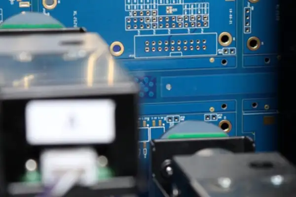
The ramp rate was pushed up at 3°C per minute, the same as an ordinary FR4 multilayer board, and the prepreg resin gelled before it had time to fully wet the core surface — you can imagine the resulting interface bond strength.
We forced them to cut the ramp rate to 1.5°C per minute, and added a dwell plateau at 80°C to fully open the resin-flow window. During cooling, we also couldn’t allow arbitrary fast cooling, or the FR4 and the high-ceramic-filled layer’s shrinkage rhythms wouldn’t sync, and board warpage would drag placement yield straight into the abyss.
After the change, cross-section analysis showed copper peel strength visibly improved, and after a full 200 cycles of thermal cycling, no new delamination appeared.
Now, when I encounter a mixed stack-up design, I no longer ask whose datasheet looks prettier — I only care about one thing: will this factory’s press engineer draw up a cure profile custom-tailored to my specific stack-up.
Devilish Details in Surface Finish and Plating Can Ruin an Otherwise Perfect Drawing
The RF pad area on an Antenna Module Control PCB was never a spot where “shinier is better.”
Skin effect dictates that signal propagation runs almost entirely through that thin conductor surface skin depth — the moment copper foil roughness climbs even one grade rougher, insertion loss immediately jumps up. Even a few microns of plating-thickness unevenness causes impedance discontinuity that shreds your return loss.
I saw an extreme case during a vehicle radar board failure analysis: after vibration testing, the passive intermodulation value doubled with no warning at all.
We pulled connectors off one by one to investigate and found the culprit was the ENIG finish used on the board-to-board connector solder pads — the nickel layer had developed microcracks under high-intensity vibration, and the moment bare copper was exposed, it immediately formed a nonlinear junction node.
After switching to immersion silver and adding a reinforcing adhesive dot at the base of the connector body, the PIM curve instantly settled back near baseline.
Now, when selecting surface finish, I’m unwilling to take chances on any process with high nickel content and no crack-resistance data.
For antenna control boards with relatively high multi-channel power handling, electroless palladium immersion gold, though pricier per unit, delivers an extremely thin nickel barrier and a reliable, non-magnetic interface. If budget is genuinely tight, I’d rather use low-PIM immersion silver while strictly controlling sulfur-free packaging.
As for OSP, though it looks clean and tidy, it can’t withstand rework abuse — anyone who’s been burned by this knows exactly what I mean.
Expansion Compensation and Registration Precision: Tolerances You Can’t Ignore on a mmWave Radar Board
During the demo phase of a 78GHz automotive radar, a specific frequency bin kept showing unexplained deep fading.
The TDR trace showed a clear impedance notch in the via stub region. Cross-sectioning revealed the residual stub length remaining after backdrilling was nearly 150 microns — for that wavelength, that’s essentially a quarter-wave resonator sitting there causing trouble.
This taught me a lesson: registration accuracy and material-movement compensation are not optional background knowledge — the moment they go out of control, they translate directly into functional failure.
When PTFE-based core material is laminated together with FR4 prepreg, the X/Y-direction dimensional-change difference can easily exceed two thousandths. If inner-layer patterning still relies on traditional film artwork rather than LDI laser direct imaging, the film’s own environmental distortion stacked on top of material movement is essentially playing multiplication instead of addition.
Now, for every millimeter-wave antenna module control board project, I lock down an independent scale-factor compensation table in advance: separate coefficients set for different prepreg types; post-lamination X-ray targeting correction is mandatory; backdrill depth tolerance is tightened below fifty microns and must be supported by inline monitoring data.
It sounds tedious, but it’s really just putting into writing, ahead of time, what a qualified RF factory should be doing as routine practice anyway.
Why Measurement Can’t Be a Formality: TDR and Environmental Aging Are the Real Mirrors
A VNA swept S-parameter scan is neat and tidy, but it can also be dangerously deceiving.
Very often, a perfect Smith chart swept on the lab bench using an SOLT calibration kit becomes unrecognizable at the system level because of fixture de-embedding error.
So I’ve developed a somewhat unpopular habit: the moment first-article samples arrive, I don’t rush to hook up a signal generator — I always sweep a full impedance profile with a time-domain reflectometer first.
TDR doesn’t spare your feelings — it directly shakes out, right in front of your eyes, every subtle reflection spike caused by via barrel plating variation, connector transition discontinuity, or even inner-layer copper roughness.
Once, a vendor report insisted the backdrill stub was controlled within ten mils, yet the TDR waveform showed an unmistakable positive reflection peak that forced us to run destructive physical analysis — sure enough, the depth deviation was nearly three mils. This kind of thing would have been smoothed away entirely by an algorithm in the frequency domain.
I also insist that every raw TDR data file must carry a lot number and use “####” as a delimiter to separate test points, making it easy to import into our own scripts for statistical analysis. Any supplier unwilling to cooperate gets removed from our AVL immediately.
As for reliability verification, I’m not particularly superstitious about a raw thermal-cycling count number either.
For an antenna array exposed long-term to day-night temperature swings and multi-axis vibration, what’s often truly fatal isn’t a solder-joint fatigue crack somewhere, but the inter-channel phase walk-off accumulated from slow dielectric-constant drift.
So I lean toward long-term monitoring of relative phase stability across all sixty-four channels at actual operating power level, watching for any irreversible monotonic shift — that’s the method most capable of exposing insufficient design margin and hidden manufacturing defects.
How to Find a High-Frequency PCB Manufacturer Willing to Fight for Your Tolerances
By the time you’ve narrowed the field, you’ll find that the shiny equipment list displayed on a factory tour can’t shield you from a single real failure mode.
The team genuinely worth a long-term partnership is usually the one that proactively tells you, “Change this fifty-ohm line corner to arc routing and we can cut your stub risk in half” — not the one that just nods and says “sure, we can do that.”
My method for evaluating a candidate factory has now simplified to a few steps: have them send over a batch of test coupons matching my typical stack-up and critical RF feature sizes, and I personally measure insertion loss, temperature drift, impedance variation after thermal cycling, and run a multi-tone PIM sweep. At the same time, I check whether their magnetic contamination control protocol covers every link — cutting tool cleaning, line suction pipe filters, and transport packaging. I also confirm they can trace every lot of incoming copper foil back to its original smelting heat number, and that they’re willing to open all inline inspection data to our audit.
In this industry, the top-tier players who can build a genuinely stable Antenna Module Control PCB usually aren’t the ones printing the most GHz logos on their brochure — they’re the teams willing to invest enormous invisible effort into maintaining an ultra-clean environment and full process-data traceability.
Once you stop trusting the spec sheet and instead trust test data you’ve run yourself, you’ll find that what “reliable” really means is countless increments of one-hundredth stacked on top of each other.
What actually makes a long-term PCB supply chain partnership work — shared
Practical, experience-based strategies for how to reduce PCB procurement risks — from
Real factory-floor lessons on how to optimize a PCB manufacturing process —
- 중소규모 배치 생산 전문가
- 고정밀 PCB 제작 및 자동화된 조립
- OEM/ODM 전자 프로젝트를 위한 신뢰할 수 있는 파트너
영업 시간: (월~토) 9:00~18:30
Get quote, solution or any question, Andre always here to help