
Battery Monitoring System PCB: Why the Hardware Foundation Determines Everything Else
BMS reliability isn’t decided by algorithms — it’s decided by the PCB
I often feel that many people have misconceptions about the industrial control sector. I can’t help but chuckle whenever I see someone comparing the price of a smartphone motherboard to that of an industrial control PCB—they are simply not in the same league! Just think about it: if a smartphone breaks, you can usually just restart it or get a new one; but if a board in a factory suddenly fails, the entire production line grinds to a halt! The resulting losses are no laughing matter.
I recall a friend in the food packaging industry complaining about this exact issue: their automated assembly line was shut down for half a day because of a seemingly insignificant circuit board malfunction, causing them to miss all their orders for the day! Their boss eventually realized that this tiny board was the lifeline of the entire system. Now, when they make purchasing decisions, they no longer fixate on chip model numbers; instead, they focus on whether the PCB can withstand the hot, humid conditions of the workshop floor.
Honestly, I think people often overcomplicate things! In industrial control, the top priority has never been flashy features, but rather rock-solid stability. No matter how ingenious the design or how many functions it has, it’s all for nothing if the board constantly malfunctions on the production line. I’ve seen so many engineers choose cheaper board materials during the design phase to save a little money, only to have all sorts of strange problems crop up just months after installation! In the end, the combined cost of repairs and lost production time turns out to be several times higher than the cost of simply buying a higher-quality board in the first place.
Speaking of which, this reminds me of another interesting point: many factories are currently pursuing smart upgrades, yet they often overlook the fundamentals! You could install countless sensors and implement incredibly complex algorithms on a production line, but if the underlying circuit board fails to hold up, all that investment goes right down the drain. I once visited an auto parts factory, and the equipment manager shared a very practical insight: to them, a high-quality PCB is like the foundation of a house—you can build all sorts of beautiful structures above ground, but if the foundation isn’t solid, the whole thing is bound to collapse sooner or later.
That’s why I believe we shouldn’t just fixate on high-sounding concepts when it comes to industrial control. Things like artificial intelligence and big data are certainly important, but without reliable hardware to back them up, they’re nothing more than castles in the air. This is especially true now, as so many industries push for automation upgrades; prioritizing the quality of foundational hardware is paramount. After all, for a factory, stable equipment operation is the ultimate driver of productivity.
I’ve also noticed an interesting pattern: the most experienced engineers are the ones who know exactly when it’s worth spending money on critical components. They won’t risk failure just to save a little on material costs, because no one can afford the price of downtime. It’s a simple principle: if you treat a PCB as a mere consumable, you’ll only ever get consumable-grade reliability; but if you treat it as the backbone of the entire system, it will deliver a completely different level of return.
At the end of the day, industrial challenges aren’t solved by gimmicks. What’s needed is genuine durability and stability. So, the next time you see two boards that look similar but differ vastly in price, don’t jump to conclusions. Ask how long they can withstand extreme conditions—you might just realize that the option which seems a bit pricier is actually the most cost-effective choice in the long run.
I’ve always felt that many people misunderstand PCBs in the industrial control sector, often assuming they are simply “beefed-up” versions of consumer electronics boards—using slightly better materials or featuring more robust construction. That mindset is actually quite dangerous, as it completely overlooks the invisible “silent killers” present in industrial environments.
Take temperature, for instance. The phones and computers we use daily might lag or even shut down if the environment gets a little too hot or cold. But have you ever stopped to consider the conditions faced by a circuit board controlling valves in a steel mill? It might spend the better part of a day baking against a scorching furnace wall, only to have ice-cold water from a cooling system splash onto the other side. This isn’t a matter of staying within a comfortable 0-to-40-degree range; it involves violent thermal shocks over short periods. Under such repeated stress, the internal structure of standard PCB materials easily succumbs to fatigue—mismatched thermal expansion coefficients between the copper foil and the substrate cause repeated pulling and tugging, leading to the formation of microscopic cracks. Initially, these cracks might not affect operation, allowing the equipment to run normally; however, after six months or a year, a sudden short circuit on a humid morning could cause a total system failure, halting the entire production line. You see, the true test for an industrial control board isn’t just whether it functions at a specific temperature, but its “longevity and resilience”—a requirement on an entirely different level.
Then there is the issue of vibration. A home router sitting on a desk remains essentially stationary. In contrast, factory equipment—especially large-scale stamping presses, textile machines, or mining machinery—either generates intense vibration or is subjected to it continuously for years or even decades. This constant, sometimes high-frequency physical stress acts as a slow, wearing force on the circuit board. Solder joints can suffer from metal fatigue, and connections between PCB layers may gradually wear down due to minute displacements. I once encountered a case involving a drive board in an injection molding machine: long-term medium-frequency vibration caused a nearly invisible “cold solder joint” (poor connection) beneath a BGA-packaged chip. This resulted in millimeter-scale dimensional deviations in the manufactured products, and it took days of troubleshooting to pinpoint the root cause. Such issues are virtually unheard of in consumer electronics but are commonplace in industrial environments.
It is precisely because the operating environment is so complex and volatile that inspection standards for industrial control PCBs are exceptionally rigorous. Many people have heard of the IPC “Class” ratings but may not fully grasp their significance. Boards used in consumer electronics often fall under Class 1, which allows for minor imperfections that don’t affect final assembly—such as slightly misaligned silkscreen printing or a tiny bubble in the solder mask—provided the device can be assembled, powered on, and sold. In the industrial control sector, however, we typically adhere to Class 2 or even Class 3 requirements.
Moving up a “Class” isn’t just a matter of slightly raising the bar for acceptance; it represents a commitment to the product’s reliability throughout its entire lifecycle. Take trace spacing and width, for instance: under Class 3 requirements, the tolerance ranges are extremely tight. Why? Because in harsh environments, uneven etching can leave narrower sections prone to excessive heat buildup when carrying high currents over long periods; these sections become the “weak link” of the circuit, accelerating aging. Similarly, requirements for barrel copper thickness are more stringent to ensure resistance to corrosion in hot, humid conditions. While these details might appear as differences of just a few microns on a blueprint, in actual operation, they can be the deciding factor in whether a board lasts three years or ten.
In my view, selecting a qualified industrial control PCB is essentially about choosing a capability for risk management. You aren’t just buying a static circuit board; you are purchasing an insurance policy against the extreme operating conditions likely to be encountered over the coming years. The value of this policy lies in those seemingly “harsh” design rules and inspection protocols—they provide the assurance that the product will remain stable even in unseen areas. This mindset is fundamentally different from the logic driving consumer electronics, which prioritizes slimness, lightness, and “cool” aesthetics.
I often feel that people overcomplicate the subject of industrial control PCBs. Mention this field, and terms like “high reliability” and “zero defects” start flying around. It’s as if anything short of military-grade standards implies a lack of professionalism.
In reality, the “Class” classification system is an excellent tool; it provides a common framework for discussion. The problem arises when we treat it merely as a rigid hierarchy label. Take Class 2 boards in industrial control, for example—people often instinctively view them as a step up from consumer electronics but still not quite “high-end” enough.
That kind of thinking is counterproductive. To me, “Class” acts more like a selector for finding a dynamic balance point. It helps define the parameters: what level of reliability does this application require? How much are we willing to pay for that reliability? And what level of risk can we tolerate? The real decision-making process involves far more than simply picking a number.
Let me give you an example. I once encountered a team developing environmental monitoring equipment for small factories. From the very beginning, they agonized over whether to use higher-standard materials and manufacturing processes to “guarantee absolute reliability.” They eventually conducted a pragmatic analysis: their sensor nodes were installed in well-ventilated workshops; while there were many nodes, each covered only a small area. Even if a node occasionally malfunctioned—causing a brief data interruption—the system could compensate using data from other nodes.
To some, their final choice might have seemed “low-end”: they opted for lower-cost solutions for certain non-critical signal lines, reallocating the savings toward isolation protection for power management and communication interfaces. They realized that the primary source of interference on-site was actually voltage fluctuations caused by motor start-stop cycles, rather than extreme ambient temperatures.
This choice reflects a “Class” mindset—not a rigid hierarchy, but an approach based on risk control and resource allocation tailored to specific scenarios.
Therefore, rather than obsessing over abstract standards, it is far better to spend time understanding the actual environment in which your board will operate.
Will your equipment be placed in a climate-controlled server room or a dusty, vibration-prone mining workshop? What are the consequences of failure? Does it mean an hour of downtime for a production line, or does it pose a safety risk? The answers to these questions matter far more than simply chasing a high-grade label.
The essence of industrial control lies in “control” itself—making appropriate responses based on objectives, rather than pursuing perfection regardless of cost.
Sometimes, building equipment that runs reliably for a decade using “Class 2” manufacturing standards is a far greater success than attempting a “Class 3” project that collapses due to excessive costs.
Striking this balance is the true test of a designer’s or manufacturer’s expertise.
Whenever I look at the circuit boards inside complex industrial equipment, I wonder: why do they always look a bit more “plain” than the motherboards in our smartphones? It wasn’t until I worked on a few projects myself that I understood—it has nothing to do with being plain or fancy. Many people assume that designing industrial circuit boards is simply a matter of using robust materials and making the boards larger, but that is far from the truth. I used to think the same way and learned the hard way. Once, to cut costs, I used a standard consumer-grade PCB to control a small motor; it failed within days. Externally, it looked fine, but upon disassembly, I found the solder mask had become sticky from machine oil exposure, and its insulation performance had significantly degraded. I later realized that industrial environments are rife with cutting fluids, lubricants, and various chemical vapors—conditions that ordinary materials simply cannot withstand.
This made me realize a crucial point: the design philosophy for industrial control PCBs operates on a completely different logic than that of consumer electronics. While consumer electronics prioritize extreme miniaturization and high-frequency performance, the industrial sector values stability and durability above all else. Just imagine a production line grinding to a halt for half a day due to a faulty circuit board; the resulting financial loss could far exceed the cost of the board itself. Consequently, when selecting materials, we don’t obsess over the latest, flashiest technologies. Instead, we rigorously verify whether a material can withstand high temperatures, humidity, vibration, and unexpected chemical corrosion over a span of ten or even twenty years.
Take the solder mask—a fundamental component—as an example. Many view it merely as a green protective coating, but there is actually a great deal of technical nuance involved. A high-quality solder mask must provide insulation while also possessing elasticity. Industrial equipment often generates significant vibration during operation; if the coating is too brittle, microscopic cracks may develop over time. Once cracks appear, moisture and dust can seep in and corrode the underlying circuitry. Furthermore, the material must withstand repeated thermal expansion and contraction. Some equipment experiences drastic temperature fluctuations—such as outdoor controllers that might reach 60 or 70 degrees Celsius under the summer sun and drop below freezing in winter. If the coating were to delaminate after just a few cycles of expansion and contraction, it would be completely unsuitable. Regarding the PCB material itself, there is a common misconception: whenever high performance is mentioned, people immediately think of ceramic substrates or specialized composite materials. While these new materials certainly have their advantages, proven, high-quality FR4 combined with the right manufacturing processes is actually reliable enough for the vast majority of industrial applications. The key is to truly understand your operating environment. For instance, in a dusty workshop, you might prioritize arc resistance, whereas for equipment located near the coast, resistance to salt-spray corrosion becomes the primary concern. There is no one-size-fits-all answer here; judgment relies on experience and an understanding of the actual site conditions.
I’ve also noticed an interesting phenomenon: sometimes, obsessively pursuing “superiority” in a single metric creates new problems. Take increasing copper thickness to handle high currents, for example. While this boosts current-carrying capacity, it complicates manufacturing. Excessively thick copper foil leads to severe undercutting during etching and makes trace width precision harder to control. It also increases the board’s overall weight and thermal mass, posing new challenges for the soldering process. Consequently, truly experienced engineers won’t simply pile on more copper; instead, they comprehensively evaluate whether the same goal can be achieved by optimizing the layout, increasing the number of vias, or employing a better thermal management design.
Ultimately, creating a high-quality industrial control PCB is more akin to a systems engineering project. It tests not just your mastery of cutting-edge technology, but your ability to find the most stable balance point amidst various competing constraints. This balance point might not offer the highest performance or the lowest cost, but it is the choice that ensures the equipment operates reliably over the long term in that specific environment. This process involves little “showing off”; it requires patience, caution, and a commitment to detail. To me, that is the true charm of the industrial sector: it doesn’t seek momentary dazzle, but rather enduring reliability that stands the test of time.
I’ve always felt that many people have a somewhat skewed understanding of industrial control PCBs. They tend to fixate on impressive-sounding technical specifications—like how thick the copper layer needs to be to be considered “top-tier,” or the use of expensive, low-loss materials. In reality, the factors that truly determine whether an industrial control board can withstand five or ten years of harsh operating conditions are often far less flashy.
I’ve seen countless projects that were designed with all the bells and whistles—incorporating every high-end solution imaginable—only to fail miserably once deployed on the factory floor. Where does the problem lie? Often, it stems from the most fundamental aspects—the very ones most easily overlooked. Take the PCB itself: it is perfectly valid to focus on making circuits finer and denser to achieve the high level of integration required for complex control tasks. However, if you fail to consider the operating environment—such as next to an oily machine tool, beneath a constantly vibrating conveyor belt, or inside an outdoor cabinet subject to extreme temperature fluctuations—then even the most precision-engineered circuitry can short-circuit due to a simple issue like condensation.
So, my view is that for industrial control boards, reliability always takes precedence over performance. That’s not to say performance isn’t important—far from it—but rather that performance must be built upon a foundation of stable operation. Just imagine a chemical plant production line grinding to a halt because a control board succumbed to moisture; the resulting losses would go far beyond the simple cost of replacing the board. This brings us to what is commonly known as “conformal coating.” I feel that likening it to mere “protective armor” doesn’t quite do it justice; it is more akin to outfitting the circuit board in a custom-fitted, all-weather protective suit.
Many people assume that conformal coating is just a matter of brushing on a layer of glue to keep out dust and moisture. In reality, there is a lot more nuance involved. You have to make your choice based on the specific application. For instance, if your equipment will be exposed to chemical solvent vapors, you need a coating with exceptional chemical resistance. If it operates in a high-vibration environment, the coating’s flexibility and adhesion become critical. And for outdoor locations with significant day-night temperature fluctuations, the coating’s ability to withstand thermal cycling without cracking is the key factor.
I encountered an interesting case involving a control system used on a crane at a coastal port. The original boards lacked conformal coating, and within six months, salt spray caused corrosion to form between the fine-pitch pins, leading to signal interference. During the redesign, they not only selected the right coating material but also paid close attention to the application process itself. Instead of simply dipping the entire board or spraying it indiscriminately, they used precise masking to protect areas that didn’t need coating, such as connector sockets and heatsink mounting holes. That detail is crucial; otherwise, you might finish coating the board only to find that plugs won’t fit or heatsinks can’t be installed—which would be a truly embarrassing situation.
This actually highlights a deeper issue: when developing industrial products, we cannot view design and manufacturing in isolation. The conformal coating process should be taken into account right from the PCB layout stage! Have you allowed for sufficient creepage distance for the coating? Is the component layout conducive to uniform spraying or dipping? Will tall electrolytic capacitors create “shadow zones” where the coating fails to reach the area behind them? These are all factors that require advance planning. Ultimately, a truly reliable industrial control PCB is not a work of art for the laboratory; it is a soldier ready for the battlefield. Its design philosophy must be rooted in the mud, wind, rain, and physical shocks it will face in the real world. When you embed reliability into every step—from material selection and circuit layout to the final protective coating—you often find pragmatic, down-to-earth solutions to the classic dilemma of balancing “high-frequency/high-speed” performance against “low cost.” You realize what the non-negotiable lifeline is: not the highest performance specs on paper, but the reliable “heartbeat” that ensures stable control execution under the harshest conditions.
I often feel that many people have a skewed understanding of industrial control PCBs. Whenever the topic comes up, people love to rattle off high-end technical specs or complex manufacturing processes, as if sounding overly technical is the only way to prove their expertise. Yet, in my experience, the factors that truly determine whether a PCB can withstand three to five years on the factory floor are rarely the cutting-edge bells and whistles.
Take the protective coating applied to the PCB, for instance. People frequently recommend fancy-sounding “lacquer-like” materials. I’ve seen many engineers swayed by suppliers into choosing expensive, novel coatings, only to have them peel or crack within months due to environmental oil or temperature fluctuations. It turned out the problem wasn’t the material quality itself, but a fundamental mismatch in the coefficient of thermal expansion between the coating and the PCB substrate. A few cycles of the machine starting, stopping, and alternating between hot and cold were enough to cause failure at the interface. You won’t find these nuances clearly spelled out in a datasheet; you have to test it yourself—and sometimes learn the hard way.
This reminds me of the current hype surrounding AI. Many factory owners believe that installing an AI system will instantly elevate their production line’s intelligence. The reality, however, is that if the underlying industrial control PCB design cannot keep pace with the required computing power or data transmission demands, even the most sophisticated AI algorithms will go to waste. I recall a classic case where a factory wanted to implement AI-based visual quality inspection. They purchased expensive software and cameras, only to find the image processing plagued by lag and stuttering. After much troubleshooting, the culprit turned out to be an outdated controller on the production line. Its PCB layout relied on decade-old design principles; the signal bandwidth was woefully inadequate, causing data to struggle just moving across the board—by the time it reached the processor, it was already too late.
That’s why I believe that rather than chasing the most impressive technical specifications on paper, it is far better to understand the actual environment where the PCB will operate. Will it be installed in a coastal workshop exposed to salt spray? In an unheated warehouse during a Northeast winter? Or inside high-vibration equipment running 24/7? These specific scenarios dictate entirely different priorities.
Sometimes, the safest choice is a time-tested solution rather than the latest product release. Of course, this doesn’t mean rejecting new technology; it simply means doing your homework thoroughly before making a decision, rather than getting swept up in trendy concepts. After all, in industrial control, stability and reliability always come first—everything else takes a back seat.
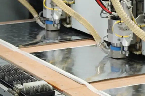
I’ve seen far too many factories run into trouble by choosing the wrong PCB supplier simply to save a little money. It’s like frying your smartphone’s motherboard because you bought a cheap knock-off charger to save a few hundred yuan—the cost of the damage far outweighs the initial savings. PCBs for industrial control are a completely different breed from those used in consumer electronics; they must operate flawlessly for years in environments characterized by vibration, dust, and drastic fluctuations in temperature and humidity.
Many people focus on haggling over the price quote the moment they start discussing suppliers. That’s a risky approach. Just think about it: if a single faulty board causes a one-hour production line stoppage, the financial loss could easily exceed the entire cost difference of the batch. And that’s not to mention hidden issues—like a batch made with inferior materials that passes initial testing but develops intermittent faults after six months of operation, turning troubleshooting into a nightmare. I know an equipment manufacturer that learned this lesson the hard way. In an effort to cut costs, they switched to a cheaper supplier; while the first batch passed all pre-shipment tests, the failure rate skyrocketed to 15% within three months of installation at the customer’s site. Their after-sales team was constantly on the road, and the travel and labor costs alone far exceeded the initial procurement savings.
A truly reliable supplier will proactively discuss how they control their production environment—covering details like workshop temperature and humidity regulation and anti-static measures. I once visited a PCB factory we had worked with for years; the operators wore gloves even when handling the boards, and one pointed to the floor, telling me, “We even monitor dust particle counts here.” That kind of attitude inspires confidence. A top-tier industrial control PCB supplier won’t just harp on about having certifications; instead, they can clearly specify the source of their base materials, copper thickness tolerances, and the brands of solder mask ink they use.
During the sample testing phase, don’t just check for basic functionality. I make it a habit to put samples into a constant temperature and humidity chamber for a week before testing their performance. Experienced suppliers understand this rigorous approach—they often conduct even harsher aging tests themselves. In contrast, suppliers focused solely on winning bids through low prices tend to push back at this stage, claiming that “standard tests have already passed, so there’s no need for such trouble.” That’s a red flag.
Ultimately, selecting a PCB supplier isn’t a one-off transaction. You need to see if they are willing to invest time in understanding your application scenario and offer professional advice when questions arise about your design, rather than simply saying, “We just do whatever the customer asks.” The circuit boards powering those machines—running day in and day out—must be as reliable as a cornerstone. That reliability isn’t achieved through low-price bidding wars; it is built upon the supplier’s obsessive attention to every single process detail.
BMS reliability isn’t decided by algorithms — it’s decided by the PCB
Beamforming performance depends on phase coherence across every antenna element — and
A relay control board that works perfectly in the lab can fail
- 중소규모 배치 생산 전문가
- 고정밀 PCB 제작 및 자동화된 조립
- OEM/ODM 전자 프로젝트를 위한 신뢰할 수 있는 파트너
영업 시간: (월~토) 9:00~18:30