

What Documents Are Required for PCB Production: A Field Guide From Real Industrial Weighing Controller PCB Projects
Many engineers focus too much on technical parameters early on and overlook
I’ve always felt that the most troublesome thing about making flexible circuit boards is those seemingly insignificant details. I just finished a project last week and almost had to rework it because of poor impedance matching. Often, we focus too much on the circuit layout and ignore the impact of the material’s inherent properties on signal quality.
The thickness variation of flexible boards is more subtle than imagined. Once, we sent samples for testing and found that the impedance values of the same design varied by up to 8% across different batches of boards. We later realized that the polyimide substrate, affected by the hot-pressing process during molding, experiences micron-level thickness fluctuations—an amount sufficient to cause reflection problems for high-frequency signals.
Performance under bending conditions further tests design skills. I’ve seen too many cases where engineers only calculated static impedance, resulting in signal integrity failure when the device was bent during assembly. Once, a customer complained that their wearable device experienced data packet loss when the wrist was bent; upon disassembly and measurement, we found that the characteristic impedance at the bending point had drifted from 50 ohms to nearly 60 ohms.
Regarding the handling of rigid-flexible joints, my experience is to avoid relying too much on theoretical calculations. In one project, a 3mm stepped transition was implemented according to standards, but copper foil breakage still occurred during vibration testing. The problem was solved by extending the transition area to 7mm and using an adhesive with a more suitable elastic modulus.
In fact, the most important aspect of flexible circuit design is an intuitive understanding of material behavior. For example, knowing what bending radius will cause irreversible deformation of the dielectric layer, or how to arrange the layers to bring the neutral axis closer to the signal layer—experience is often more useful than formulas.
Recently, I’ve started trying to incorporate bending simulations into the simulation phase. Although the computational load has increased significantly, at least we can identify the hidden problems early on. After all, nobody wants to be proven wrong only at the trial production stage, right?
Designing flexible circuit boards is quite interesting. Many people think that simply drawing the circuitry is enough. In reality, there are far more factors to consider than imagined.
I’ve seen many engineers directly apply the rigid board approach to flexible boards. The result is that the prototype malfunctions as soon as it’s bent. This is especially true for applications requiring repeated folding, such as connectors inside wearable devices. Simply calculating the theoretical minimum bending radius without considering actual usage can easily lead to problems.
The choice of copper foil is often underestimated. Different types of copper exhibit significantly different performance when bent. Some customers choose unsuitable materials to reduce costs, which ultimately increases after-sales maintenance costs.
The truly crucial aspect is understanding how a product moves throughout its entire lifecycle. Some devices might be bent hundreds of times a day, while others might be assembled and never used again. The design approaches for these two scenarios should be completely different.
I recall a medical device project where the impact of the cover film on the bending radius was overlooked, leading to low yield rates during mass production. We only resolved the issue by adjusting the material thickness.
In dynamic applications, the most easily overlooked problem is uneven stress distribution in the bending area. Sometimes, excessively small bending angles in certain areas can cause the copper foil in those locations to experience unexpected tensile forces.
Temperature changes also affect material flexibility. In high and low temperature tests, we’ve found that some materials become more prone to microcracks at low temperatures.
The best advice is to conduct thorough physical testing early on, rather than relying too heavily on theoretical calculations. Many factors interact during actual bending, which simulation software struggles to fully capture.
When designing a new project, I always remind the team to hold the sample and repeatedly bend it to get a feel for the material. This often reveals problems that aren’t visible on the drawings.
Ultimately, flexible circuit board design requires an intuition about material behavior; this experience can only be accumulated through real-world projects.
I’ve seen too many people oversimplify flexible circuit boards. They think it’s just a bendable board, right? Actually, there’s a lot more to it than that.
I remember a project last year almost failed because of the reinforcement plate. To save space, we placed the reinforcement plate too close to the bending area. As soon as we received the sample, we noticed something was wrong—we could hear a faint cracking sound every time we bent it. We solved the problem by moving the reinforcement plate back a sufficient distance.
What I find truly interesting is the testing phase. Many people think that if a flexible board can be bent a few times without problems, it’s passed. But it needs to simulate real-world usage scenarios. For example, wearable devices are bent hundreds of times a day; wiring harnesses in cars may have to withstand temperatures ranging from -40 degrees Celsius to high temperatures.
I have a habit of marking key locations to observe changes. Once, I discovered that the copper foil in a certain area developed fine cracks after repeated bending; although the electrical performance was temporarily normal, it certainly wouldn’t be sustainable in the long run.
Environmental testing is often overlooked. Once, we placed samples in a high-temperature, high-humidity environment for continuous observation and discovered that blistering began to appear at the edges of the cover film; this kind of problem is difficult to detect in routine testing.
Regarding wiring, I have a different perspective—it’s not always necessary to pursue the thinnest lines; sometimes, appropriately widening them can actually improve reliability; the key is to allow for material flexibility.
Recently, I encountered a rather interesting case: the client required the flexible board to maintain a fixed shape at a specific angle; we achieved this effect by adjusting the material thickness and the position of the reinforcing sheets; this made me realize that flexible design actually has many possibilities.
The worst thing is encountering designs that cram all components into the bending area; I’ve seen people directly attach chips to frequently bending locations in pursuit of thinness; the result is predictable.
Actually, the most fulfilling moment in this industry is seeing the boards I designed work stably in various harsh environments; that feeling is much better than simply completing a project.
I think good flexible design should be like Tai Chi—seemingly soft yet full of resilience; every detail must consider the characteristics of the material itself and the actual application scenario; blindly applying standards often backfires.
I’ve always found flexible PCB design quite interesting. When I first started, I tried to simply apply the rigid PCB approach, which led to many problems. Once, while designing the internal circuitry for a wearable device, the electrical performance met all standards, but the sample developed broken lines in the third week of testing. It turned out the copper foil thickness in the bending areas was incorrect.
The most challenging aspect of flexible design is simultaneously considering both electrical performance and mechanical characteristics. For example, even if you’ve calculated impedance matching correctly, a bend changing the trace width can completely disrupt signal integrity. I prefer to leave some slack in critical bending areas, like a spring, allowing the circuitry room to breathe, rather than tightly tying it in. I’ve seen too many people cram the circuitry in to save space, resulting in adjacent lines rubbing against each other during dynamic testing, causing insulation damage.
Material selection is also crucial. Polyimide is indeed effective, but the film elongation varies significantly between different manufacturers. Once, I tried a new supplier’s substrate, which worked fine at room temperature, but became brittle and cracked at -20 degrees Celsius. Now, for low-temperature applications, I always require additional thermal shock testing, as the actual operating environment of equipment is far more complex than that of the laboratory.
Handling the rigid-flexible junction requires more finesse. In one project, the connection between the rigid plate and the flexible plate kept breaking. The problem was solved by changing the copper foil in the transition zone to a gradually stepped stress concentration pattern. Such details might only involve adding a couple of lines on the drawings, but they have a huge impact on the actual lifespan.
Recently, while designing the circuitry for medical endoscopes, I discovered a new approach—instead of pursuing an absolutely small bending radius, it’s better to leave reasonable room for movement during assembly. For example, having the flexible circuitry spirally coiled within the sleeve ensures 360-degree rotational freedom while avoiding repeated damage to the same location. This three-dimensional wiring approach is more sustainable than simply compressing the plate thickness.
In fact, the bending requirements of each product are unique. Smartwatch straps need to be bent hundreds of times a day, while automotive sensors may only bend two or three times throughout their entire lifespan. The former requires a focus on fatigue life, while the latter needs to pay attention to deformation recovery under long-term static bending. There’s no one-size-fits-all solution; the key is to clearly understand the actual usage scenarios of the equipment.
Recently, I tried adding material creep parameters to the simulation phase and found that it more accurately predicts performance degradation after long-term use. Although it increased the computational load, it was worthwhile compared to the need for mass rework later. Good flexible design should be like a dancer’s ligaments—both resilient and stable—this is the true ideal that engineers should strive for.
I’ve always felt that the most fascinating aspect of flexible circuit board design is that it breaks the traditional mindset of circuit boards. I remember when I first encountered this type of project, I habitually laid out the traces according to the rigid board approach, which resulted in significant losses. Those seemingly neat right-angle turns developed cracks after repeated bending, making me realize that flexible design requires a completely different philosophy.
Many people get bogged down in specific wiring rules, but I think it’s more important to understand the properties of the material itself. When you hold a flexible board in your hand and bend it repeatedly, you can intuitively feel which areas are under the greatest pressure. This tactile experience is more direct than any theory. Once, while experimenting with flexible circuits in wearable devices, I discovered that even with a layout strictly adhering to theoretically calculated curvature radii, malfunctions still occurred in actual use. I later realized that dynamic and static bending have completely different effects on circuits.
An interesting discovery regarding teardrop design: Traditionally, teardrops are considered simple transitional shapes, but in actual testing, I found that the rate of curvature change significantly impacts lifespan. In one comparison of two sets of samples, one using a standard teardrop shape and the other with customized adjustments, the latter showed nearly double the durability. This made me realize that every detail in flexible design deserves meticulous consideration.
Impedance control is perhaps the most easily underestimated challenge. While working on high-frequency signal transmission, I found that the impedance fluctuation of the same linewidth under different bending states could reach 20%. This was only resolved through layered design and the use of special materials. This experience made me realize that the electrical characteristics of flexible boards dynamically change with their shape.
Recently, while trying to apply ultra-thin flexible circuits in medical devices, I also discovered an interesting phenomenon: when the circuit thickness is less than 0.1mm, the traditional bending radius calculation formula becomes invalid. This made me start considering the applicability of existing design specifications at different scales. Perhaps we need to establish a more granular flexible design system?
A common misconception in flexible circuit board design is that many people believe simply making the board thinner will solve all problems. In reality, when working on wearable device projects, I found the real challenge lies in the fit between different areas.
When designing the motherboard for a smart bracelet, we were particularly troubled by the battery compartment design. The client wanted sufficient support to prevent battery displacement, yet it also needed to deform with the wristband. We tested three different thicknesses of polyimide material and found that the 0.2mm version was more durable than the 0.1mm version because slightly increasing the thickness resulted in a more even stress distribution during bending.
Reinforcement design for flexible circuit boards is not simply a matter of attaching a reinforcing sheet. I once saw a colleague directly cover the hinge area of a foldable phone with a stainless steel reinforcing sheet. The product cracked after less than 5,000 opening and closing cycles. We shifted the reinforcement area 3mm to each side of the hinge to create a buffer zone, which allowed it to pass durability tests. This kind of boundary management is more important than simply choosing materials.
Now, when I encounter designs requiring localized reinforcement, I first simulate the deformation trajectory in actual use. For example, the circuit board in a medical catheter needs to bend inside a blood vessel, so I have to consider whether the edges of the reinforcement sheet can twist and deform along with it. Sometimes, a solution that looks perfect on paper reveals problems once it enters the lab.
A recent automotive sensor project made me realize the complexity of flexible design. The circuit board needs to withstand the high temperatures and vibrations of the engine compartment and bend in a confined space. We ultimately used a multi-layered thin copper foil stacking solution, which controlled the overall thickness while ensuring heat dissipation. This flexible approach is much more practical than applying standard solutions.
The real test of skill lies in making the hard parts strong enough and the soft parts flexible enough, with a seamless transition between the two. The most successful project I’ve handled was actually one that abandoned traditional reinforcement methods and used cutouts in frequently bending areas to distribute stress over a larger area. This unconventional approach unexpectedly improved the product’s lifespan.
When designing flexible circuit boards, many people easily overlook one issue—the direction of the circuit bend is actually more important than the bending radius. I’ve seen too many engineers focus solely on calculating the minimum bending radius, resulting in disastrous outcomes. Once, our team’s design for the circuitry in a smartwatch wristband resulted in a production yield dropping to 30% because we didn’t pay attention to the angle between the copper foil traces and the bending direction.
Imagine the difference between folding a piece of paper horizontally and vertically. When folded horizontally, the paper bends naturally; when folded vertically, wrinkles easily form. The same principle applies to flexible circuits. When the bending direction is perpendicular to the copper foil traces, the tensile force on the conductive layer is most even, while parallel bending creates stress concentration points at the circuit edges.
Especially in dynamic bending scenarios, such as the hinge design of foldable phones, we conducted comparative tests and found that the lifespan of samples with optimized trace direction increased by more than five times. This is far more effective than simply pursuing thinner substrate materials because even the best materials cannot withstand repeated incorrect stress patterns.
Now, when faced with designs requiring repeated bending, I first hold a physical sample to simulate actual usage scenarios and feel the differences in flexibility in different directions. This method, while seemingly unprofessional, often reveals problems that are not visible on drawings and sometimes even detects structural interference in advance.
The essence of flexible design lies in understanding the match between material properties and motion trajectories, rather than obsessing over parameter specifications. Just like clothing, even the best fabric will feel awkward if the cut is ill-fitting.
When it comes to flexible circuits, I always feel that many people complicate simple problems. I’ve seen too many engineers immediately get bogged down in material parameters, neglecting the most basic design intuition.
I remember once helping a client modify a smart bracelet design. Their original plan was to attach the battery directly to the flexible area, but repeated bending during testing caused the connection points to crack. Actually, a slight adjustment to the layout, placing the vulnerable components in the reinforcement positions, could have solved 80% of the problem. The essence of flexible design is understanding which parts need to move and which parts must remain stable.
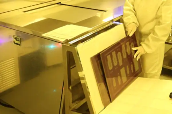
When assembling circuit boards, I usually simulate bending trajectories by tearing paper by hand. This method, though crude, is incredibly effective. Once, I discovered that a client’s connecting bridges were concentrated on the same axis; changing them to a staggered distribution resulted in immediate stress dispersion. Now, seeing those neatly arranged grid-like boards makes me laugh—they’d definitely break in droves on the production line.
Regarding corner treatment, I don’t think it’s necessary to rigidly adhere to the 0.5mm radius standard. I worked on an industrial sensor project where space constraints limited the corner radius to 0.3mm. Later, we added a teardrop-shaped copper foil reinforcement at the corner, and it worked flawlessly for three years. Rules are rigid, but the ductility of materials is flexible.
Lately, I’ve increasingly favored using wavy routing in dynamic bending areas, as it absorbs deformation energy like a spring. I once tried serpentine routing in a medical catheter project, and it improved durability by more than five times compared to straight lines. However, it’s crucial to control the curvature of the peaks and troughs; too gentle and it’s ineffective, too sharp and it easily leads to stress concentration.
Many people are perfunctory about documentation annotations, but I insist on using different colors to distinguish static and dynamic areas on the drawings. Last year, a project resulted in a batch of returns because the manufacturer misplaced the reinforcing plates. Now, not only is the bending radius specified, but the bending frequency must also be clearly stated, such as specific instructions like “≤20 bends per day.”
The most challenging aspect of flexible circuitry is spatial imagination. I often treat circuit boards like fabric. Once, I got inspiration from tailoring a cheongsam, leaving allowance at the seams to accommodate deformation—a more flexible approach than textbook methods. After all, circuits are ultimately mounted on three-dimensional objects; two-dimensional thinking is insufficient.
Many design guidelines still emphasize standardization, but truly effective flexible solutions are custom-made. Like a tailor making clothes, a ready-made suit will never fit as well as a bespoke one. Understanding the bending and stress the product will endure before starting work is more useful than memorizing a hundred specifications.
Recently, I’ve been experimenting with mixing materials of different moduli in flexible areas, layering them like a crepe cake. The transition zone design is particularly crucial at the junction of rigid and flexible parts; poor handling here can lead to fatigue fracture. However, once you master the tricks, the resulting circuits can be as resilient as rubber bands.
Ultimately, mastering flexible design requires a craftsman’s mindset. Don’t always focus on simulation data; hands-on trial and error is far more effective than any theory. I always keep various scraps in my studio. When a new idea comes to mind, I cut a couple of slices to test the feel; this physical feedback is much more realistic than a computer model.
By the way, don’t be fooled by the term “flexible.” The parts that need to be rigid must be firm. I once saw someone put a chip in a bending area—it’s practically suicidal design. A good flexible board should be like a human joint, allowing for flexible rotation while also providing skeletal support.
Over the years of designing flexible circuit boards, I’ve noticed a fascinating phenomenon: many people rush into drawing circuit diagrams and laying out the wiring, neglecting the most fundamental issue of material selection. In fact, the most crucial factors in flexible circuit board design are often these seemingly insignificant raw material choices.
Take polyimide, for example. This material is quite unique; unlike ordinary plastics, it doesn’t deform when heated. I remember once testing a polyimide sample in a high-temperature environment for over ten hours, and its dimensional change was negligible. This stability is crucial for precision equipment, especially when the line spacing is extremely small—even a deviation of a fraction of a millimeter can render the entire board unusable.
Speaking of thickness selection, I find the 12.5-micron specification particularly interesting. Initially, I thought such a thin material must be very fragile, but in reality, it strikes a delicate balance between flexibility and strength. Once, we needed to design… A connection that required repeated bending used a 12.5-micron substrate with a special copper foil treatment. That product ultimately passed tens of thousands of bending tests, making me realize that the potential of materials often exceeds our imagination.
The choice of copper foil is also a topic worth exploring in depth. Different types of copper foil have a significant impact on circuit performance. I’ve seen too many cases where choosing the wrong type of copper foil led to various problems in actual use, such as loss during high-frequency signal transmission or breakage after repeated bending. These problems often only become apparent in later testing, but by then, redesigning is very costly.
In fact, the longer I work in this industry, the more I realize that materials science is the true core technology. Sometimes a small material adjustment can significantly improve the performance of an entire product. However, this requires designers to have a deep understanding of material properties, rather than simply applying existing design specifications.
I’ve seen too many flexible circuit boards scrapped because of neglecting details. Sometimes the most troublesome thing isn’t the circuit itself, but those seemingly insignificant structural defects.
Take reinforcement, for example. Many people think that simply attaching a rigid sheet will suffice, but after a few cycles of thermal expansion and contraction, it delaminates. The key is to ensure that the reinforcing material and the base material coexist harmoniously. It’s like adding a wooden board to the bottom of a spring mattress; it can’t be too soft to provide support, nor too hard to damage the springs.
I remember once debugging a device that required repeated bending, and the customer complained that the connections kept cracking. We later discovered the problem was in the design of the transition area—the right-angled boundary was essentially a stress concentration point. We changed the edges to rounded shapes, like pre-creasing the creases at the corners of paper; the flexibility was actually better utilized.
Regarding tear-resistant design, my experience is that prevention is worse than cure. We once tried a special strain-release structure on a wearable device, and the effect was much better than simply adding tear-resistant grooves. This is like leaving buffer space at the stress points of a rubber band, rather than letting it be stretched directly at its weakest point.
Speaking of specific flexible PCB design considerations, I think the most important thing is to treat the circuit board as a breathing, living thing. It needs to operate in various states, so every bending radius and the stress at every fixing point must be carefully considered, like tailoring a suit for a person.
Once, when dealing with particularly thin flexible boards, we discovered that conventional reinforcement methods actually created new vulnerabilities. We later switched to a gradually thickening, localized reinforcement approach, much like performing stent surgery on a weak point in a blood vessel—strengthening critical areas while maintaining overall flexibility.
These experiences taught me that flexible design requires breaking free from the rigid circuit mindset. Sometimes, the most robust solution is to allow the material appropriate room for deformation. This is similar to the principles of life—excessive rigidity leads to breakage, while maintaining appropriate flexibility allows for long-term sustainability.
In fact, good flexible design is like choreography; it requires ensuring each movement is precise while maintaining a smooth and natural flow. Abrupt transitions are like pauses in a dance, while elegant curved boundaries and reasonable strain relief are key to maintaining the board’s graceful shape over time.
I’ve seen too many people oversimplify flexible circuit board design. They think that simply making ordinary circuits thinner will allow for bending and twisting—this kind of thinking will inevitably lead to failure.
I remember once taking over a smart bracelet project team that left behind a mess. To save costs, they used ordinary electrolytic copper, and by the third week of testing, the product was experiencing intermittent signal issues. Upon disassembly, I found the wiring at the bends was riddled with fine cracks, resembling a dried-up riverbed.
Truly reliable flexible design starts with understanding the properties of the materials. For example, rolled copper foil is inherently suitable for dynamic bending scenarios. Its grain structure, after being rolled, is like a layered cake, allowing stress to be evenly distributed during bending rather than concentrated on a single weak surface. We later used this material in medical monitoring equipment; that wristband was bent thousands of times a day, and after two years, the wiring remained intact.
But choosing the right material alone isn’t enough. I used to stubbornly believe that the cover film was just a protective layer until a prototyping session revealed that the circuitry became brittle at low temperatures. Tearing off the cover film revealed uneven adhesive distribution, causing localized stress concentrations. Now, I pay special attention to the thickness of the adhesive layer, just like when kneading dough—too much flour will crack, too little will make it sticky—a delicate balance requires repeated adjustments.
There’s a small detail that’s easily overlooked: the routing of circuitry in bending areas should ideally have an arc transition. Right-angle bends are stress concentration points. I’ve seen people bend sensor circuitry into the motherboard at right angles, and the samples broke before even leaving the lab. Later, they changed it to a 45-degree bevel with rounded corners, doubling the lifespan. Nature has already taught us this – look at the veins of a leaf; there are no straight bends.
The most troublesome issue is thermal management. Heat dissipation on flexible boards is much more difficult than on rigid boards. I’m used to leaving breathing space around heat-generating components, like giving circuitry loose clothing rather than tight-fitting garments. After all, if heat can’t dissipate when materials repeatedly expand and contract, it will accelerate aging. These experiences are lessons learned through real effort.
Sometimes, I feel that flexible circuit design is more like a dialogue with the material. You have to feel its elastic limits and understand its memory characteristics affected by the rolling process. After all, we’re not designing cold, lifeless circuits, but a lifeline that breathes with the device.
As for flexible PCBs, I always feel that many people overcomplicate it. Actually, after working with them for a while, you’ll find that the most crucial thing is to start from the actual application scenario. Last week, while debugging a board for a wearable device, I experienced this firsthand. The theoretical number of bends and the wear and tear in actual use are completely different things.
I remember when I first started working with flexible PCBs, I always thought the denser the traces, the better. Later, I realized that this approach could easily lead to stress concentration. Now, I intentionally leave more space in bending areas to allow for a natural transition of the traces. Sometimes, I even have to sacrifice some wiring density for a longer lifespan.
Material selection is also quite interesting. Once, to save costs, I chose a cheap material, which resulted in cracks in low-temperature environments. Since then, I’ve understood one thing: the design of flexible PCBs cannot only focus on electrical performance; mechanical characteristics are often more important.
Speaking of trace layout, I think the most easily overlooked aspect is the treatment of the rigid-flexible interface. If this area is poorly designed, even the best materials are useless. I usually add several layers of protective film in this area; although it increases the thickness slightly, it significantly improves reliability.
A recent project I’ve been working on has given me a new understanding of flexible PCBs. The client requires it to operate in humid environments, which involves balancing moisture protection and heat dissipation. Sometimes solving one problem leads to a series of new ones, and this chain of challenges actually makes design work more interesting.
In fact, after working in this field for a while, you’ll find that every project has unique requirements, and there’s no one-size-fits-all solution. The key is to maintain an open mind and be willing to adjust your design approach based on the actual situation; this is crucial for creating successful flexible PCBs.
I’ve always found flexible circuit board design particularly interesting. Many people might think it’s just about drawing lines and routing. But after getting my hands on it, I discovered there’s a lot more to it than that. Take the most basic material selection, for example. When choosing copper foil, you have to clearly understand the performance requirements of the application scenario. If repeated bending is needed, you have to consider materials with better ductility rather than just conductivity. Sometimes, you have to make many trade-offs to balance cost and performance.
Once, our team took on a project that required fitting a complex circuit system into a very limited space. The biggest challenge was how to securely place the main control chip without affecting the overall structural flexibility. Ordinary soldering methods definitely wouldn’t work because bending would easily cause problems. Later, we tried several fixing methods and finally found that using a special adhesive with a specific wiring layout yielded the best results. This process made me realize that flexible design really can’t just focus on the circuit itself; the mechanical characteristics of the entire system must also be considered.
Another time, designing wearable devices gave me a new understanding of substrate thickness. Everyone pursues thinner is better, but in practice, we found that being too thin can bring new problems, such as increased processing difficulty and decreased yield. Sometimes, appropriately increasing the thickness slightly can significantly improve overall reliability—this is probably what is meant by “too much of a good thing.”
Now, I see flexible circuit board design more as a continuous balancing act. Finding the optimal balance between electrical performance, mechanical properties, and cost has no standard answer; each project requires rethinking. Sometimes the simplest solution is the most effective; the key is to truly understand the impact behind each design choice.
Recently, I’ve seen some new products that embed components directly inside the substrate, which has been quite inspiring. Although I haven’t tried it in my own projects yet, this approach certainly opens up new possibilities. Perhaps next time I encounter particularly challenging space constraints, I can explore this direction.
Ultimately, good flexible design should be so seamless that its presence is imperceptible, reliably and naturally integrated into the product – perhaps this is the highest level of design.
While working with flexible circuit boards, I noticed an interesting phenomenon – many people focus excessively on the numbers on the material specifications sheet, neglecting the subtle differences in actual applications. I remember once a customer brought two samples for comparison; the performance differences were striking, yet the lab data were almost identical. Upon disassembly, we discovered the problem lay in the adhesive layer between the substrate and the copper foil.
That transparent gel-like substance performed perfectly at room temperature, but delaminated during continuous bending tests. This made me realize that flexible design considerations must go beyond static parameters and consider the interaction between materials in motion. For example, the bending life of the same thickness of polyimide substrate can differ by more than three times depending on the type of adhesive used.
Once, during a visit to a medical device factory, I saw their endoscope circuit boards undergoing thousands of bends daily. The engineers told me they eventually abandoned the standard adhesive and switched to a custom-formulated elastomer material, doubling the cost, but solving the breakage problem caused by repeated bending. These cases further convinced me that the success of flexible circuits often lies in those easily overlooked details. Now, when I encounter a new flexible project, I first ask a few key questions: What bending frequency does the device need to withstand? Are there temperature fluctuations in the working environment? Is there any possibility of contact with chemical solvents? These factors directly affect the selection of adhesives and substrates.
A composite material I recently tested was quite interesting. It produces minute deformations when bent, thus dispersing stress points. Although its initial flexibility is not as good as traditional polyimide, it performs more stably in long-term dynamic testing. This again proves that sometimes sacrificing some parameters can achieve better overall performance.
Truly reliable flexible design requires viewing materials as dynamic systems, not isolated lists of parts. Just as good dance partners need perfect coordination, each layer of material on a circuit board must find a harmonious way to cooperate when bending.
Designing flexible circuit boards is actually quite interesting. When I first started, I thought it was similar to a regular PCB, just thinner and softer. Later, I discovered it was completely different.
Once, when I tested a board I designed for a wearable device, it bent a few times and I found that the signal was malfunctioning. Upon disassembly, I found that the traces were cracked. That’s when I truly understood that the core of flexible board design lies in anticipating deformation.
Many people think that simply making the circuit thinner will allow it to bend, but the key is how to handle the stress on the material. For example, if the routing direction is parallel to the bending direction, each bend will put a lot of pressure on the copper foil edges, making it prone to breakage from the edges over time.
Later, when I worked on projects, I paid special attention to adjusting the routing of the main signal lines to be perpendicular to the bending axis. This resulted in much more even stress distribution, allowing the copper foil’s inherent ductility to be fully utilized.
Another easily overlooked point is that flexible boards perform differently at different temperatures. Once, during high and low temperature testing, I found micro-cracks at the joints, which turned out to be due to a mismatch in the thermal expansion coefficients of the materials. These details require experience gained through actual projects.
Now, I have immense respect for those designs that skillfully utilize flexible circuits. Behind it all lies a deep understanding of material properties and mechanical structures. Every successful case is the result of countless pitfalls and lessons learned.
Many engineers focus too much on technical parameters early on and overlook
As someone who has worked in PCB outsourcing for years, I’ve found
Cramming a camera, amplifier, dual-mic array, and Wi-Fi radio into a palm-sized
- 중소규모 배치 생산 전문가
- 고정밀 PCB 제작 및 자동화된 조립
- OEM/ODM 전자 프로젝트를 위한 신뢰할 수 있는 파트너
영업 시간: (월~토) 9:00~18:30
Get quote, solution or any question, Andre always here to help