

What Documents Are Required for PCB Production: A Field Guide From Real Industrial Weighing Controller PCB Projects
Many engineers focus too much on technical parameters early on and overlook
I’ve seen too many teams treat reliability testing as a mere formality for inspections. The way they check off standard checklists reminds me of last-minute cramming in school—memorizing knowledge points perfectly but stumped by application problems. For example, a team developing in-vehicle entertainment systems once boasted to me that their ECU passed a 48-hour random vibration test. However, user feedback indicated screen flickering during high-speed driving. It was later discovered that a solder joint on a BGA package on the PCB broke under resonance at a specific frequency.
Standardized vibration test parameters are sometimes like flowers in a greenhouse; the simulated waveforms in the lab are too regular. Real-world bumps and vibrations don’t follow the script. I prefer having engineers take samples to actual road conditions to collect real vibration spectra and then adjust the test plan accordingly. Although this takes an extra two weeks, it’s much better than a product recall after launch.
Temperature cycling tests are similar. Many people think that alternating between hot and cold temperatures a few times will solve the problem, but they overlook a crucial factor: the heat generated by components under power creates localized hot spots. This dynamic temperature field is completely different from static aging. A very interesting example is an industrial controller that survived 1000 hours in an environmental chamber with a 60-degree temperature difference, but after three months of operation in a customer’s factory, capacitor bulging occurred because the power module was operating at 87 degrees Celsius for an extended period, even though the actual power consumption wasn’t applied during the test.
The project team I lead now breaks down PCB reliability testing into several levels. Basic, routine tests are just the entry point; the real key is a customized approach tailored to the product’s usage scenario. For example, when performing salt spray testing on offshore wind turbines, low-frequency vibration is added to simulate the accelerated corrosion effect of tower sway on the circuit board. These non-standard tests often expose the most hidden defects; after all, the real world never presents you with a single-choice question.
Recently, while helping a client optimize the testing process for autonomous driving domain controllers, I discovered a significant difference in how traditional automakers and emerging companies approach ECU verification. The former tends to extend the time for individual tests, while the latter focuses more on the impact of multi-stress coupling. In fact, both need to be balanced. Just like cooking, you need to control the heat and understand the proportions of seasonings; simply pursuing an extreme indicator will cause you to lose sight of the overall picture.
Sometimes, when I see young engineers struggling with whether to add a certain test, I suggest they first answer this question: If this board were installed in the car you drive every day, how relaxed would you be about the testing standards?
I recently chatted with several hardware engineers and discovered a rather interesting phenomenon—everyone seems to treat standardized PCB reliability tests as a panacea. A thousand temperature cycle tests are no problem? This leads to the misconception that a product can last forever. This idea is actually quite dangerous.
Think about it: the temperature fluctuation rate in a laboratory is at most a dozen degrees per minute. But the real world isn’t that gentle. Under a car hood, the temperature can jump from -30 degrees Celsius to over 100 degrees Celsius in minutes—a much more dramatic temperature change than in the lab. Not to mention, in actual use, factors like vibration and humidity are also present. A single temperature test simply cannot simulate real-world scenarios.
The most typical case I’ve seen is an automotive device that passed all standard tests, but after only three months on the road, the solder joints cracked. Disassembly revealed that it was caused by the combined effects of high-frequency vibration and temperature changes—a complex pressure that standardized testing simply cannot reflect.
Currently, there’s a misconception in the industry that meeting standards is a guarantee of quality. In reality, those standards are more like an entry ticket, merely proving that your product meets the industry’s minimum requirements. To truly assess long-term reliability, you need to design targeted solutions based on specific application scenarios. For example, industrial equipment might need to focus on material aging under continuous high temperatures, while consumer electronics need to pay more attention to the effects of frequent temperature fluctuations.
Ultimately, standardized testing is like passing a driving test; it only means you know the basics. The real test of your skills comes in the rain, at night, or in unexpected situations. The same principle applies to PCB reliability. Don’t rely too much on standard conditions; think more about the real-world environments your product will face.
Having worked in the PCB industry for a while, you’ll notice an interesting phenomenon—sometimes the most reliable testing methods are the seemingly simplest. I’ve seen too many teams obsessed with complex mathematical models or fancy testing equipment. The truly important thing is to understand what you want to verify.
Take our project last month, for example. The client insisted we replace the traditional material with a new FR substrate. Initially, the engineers argued about what advanced testing methods to use to ensure reliability. Later, I suggested not rushing into complex testing procedures—just run samples of both materials in a high-temperature, high-humidity environment for two weeks.
And guess what? On the third day, we found the insulation resistance of the new material started fluctuating. This simple, brutal environmental testing proved more informative than any sophisticated instrument.
There’s a misconception in the industry that more complex testing equates to greater professionalism. This is especially true for high-density designs like HDI boards, where this trap is easily fallen into. In reality, reliability issues with microvia structures often stem from the most basic steps.
I remember once disassembling a batch of faulty boards and discovering that inadequate post-drilling cleaning led to residual debris causing slow corrosion within the microvias, ultimately resulting in open-circuit failure. This simple process issue was overlooked due to over-reliance on high-end testing equipment.
Ultimately, even the most advanced PCB reliability testing methods must be validated in real-world application scenarios. Not all problems require complex testing solutions; sometimes, the most direct verification method is the most effective.
The use of new materials certainly requires more caution, but we can’t stop experimenting out of fear of risk. The key is finding a balance—neither overly careless nor excessively conservative—this is the core principle for ensuring product reliability.
Many people immediately focus on making their PCB tests more rigorous, as if using every PCB reliability testing method guarantees success. I believe that instead of obsessing over testing methods, we should first clarify what true reliability actually is. I remember a project we had last year. All the specifications looked perfect in the lab, but it failed after only three months at the client’s site. Upon inspection, it turned out a tiny capacitor that wasn’t even on the test list had failed. This experience made me realize that failures often happen in the most unexpected places.
Now, when I design, I focus more on environmental adaptability. For example, boards designed for tropical regions need to consider the material expansion coefficient under high temperature and humidity; while those used in automotive equipment need to simulate the vibration effects of bumpy roads. This scenario-based thinking is more meaningful than simply applying test standards.
Sometimes, when I see young engineers proudly holding thick stacks of test reports, I always want to remind them: those standardized test conditions are like flowers in a greenhouse; the real test of reliability is always the complexity of the real world.
Recently, we’ve been trying a dynamic monitoring method, equipping key model boards with miniature sensors to collect real-time data on voltage fluctuations and temperature changes. Although it increases costs a bit, the field data collected is far more valuable than accelerated aging tests in the lab.
In fact, good reliability engineering should be like traditional Chinese medicine, emphasizing overall balance. Don’t just focus on optimizing a single parameter; consider the interactions between components. Sometimes, slightly reducing the clock frequency can extend the lifespan of the entire system by several years.
I hate hearing people say, “If it’s tested according to national standards, it’s fine.” Standards are just the minimum requirements; true reliability comes from meticulous attention to detail. For example, the same circuit layout using solder resist from different manufacturers can result in corrosion resistance differences of two or three orders of magnitude.
Ultimately, PCB reliability isn’t about post-production quality control; it’s about the design philosophy that permeates every decision from material selection to layout. When you truly understand how current flows between copper foils and how heat dissipates through the substrate, a reliable design naturally emerges.
Over the years in the PCB industry, I’ve learned that many people overcomplicate reliability. Every time I see my colleagues pulling out all sorts of precision instruments for testing, I want to laugh—a truly good board isn’t something you test.
I remember last year helping a friend redesign an industrial control board. They had spent a lot of money on a full set of environmental testing reports, but it started malfunctioning after only three months of field operation. Upon disassembly, it turned out to be an inconspicuous surface-mount capacitor that had detached from the solder joint under high temperature. This kind of problem might go undetected no matter how many PCB reliability testing methods you use, because the test environment can never simulate the randomness of real-world operating conditions.
I’m particularly annoyed by those theoretical proponents who constantly talk about reliability. They always emphasize 99.9 … Recently, I was working on a batch of automotive electronics boards. Initially, a customer requested a full 72-hour high-temperature aging test. I suggested changing it to a 24-hour basic test plus targeted vibration testing, because the actual failures of these boards mostly stem from bumpy road conditions rather than continuous high temperatures. This not only saved two-thirds of the testing time but also prematurely identified two connectors with insufficient lifespan.
Ultimately, reliability isn’t achieved by piling on test items; it should be integrated into every stage from selection to implementation. Currently, the industry relies too heavily on standardized processes, neglecting the designer’s intuition. Sometimes, asking “Where is this board most likely to fail?” is more useful than performing ten tests according to a checklist.
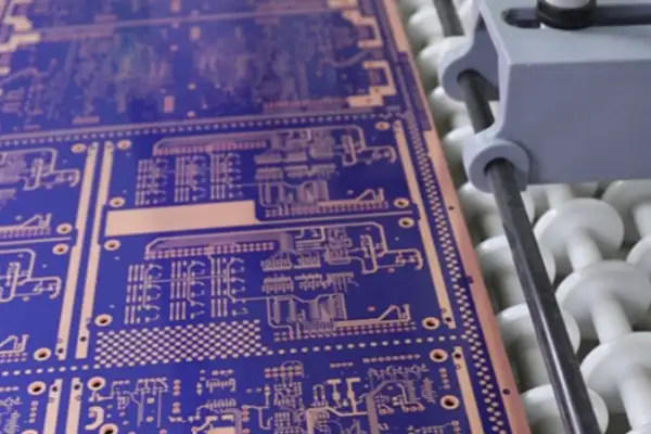
Good design speaks for itself. When you thoroughly understand the characteristics of each component and leave sufficient margin in the wiring, even without complex environmental testing, the board feels reliable. This feeling is something no amount of test data can provide.
Every time I see those standardized reliability testing procedures, I want to laugh. Do they really think that throwing a board into a high-temperature chamber for a few hours can predict its performance ten years from now? That’s like playing Russian roulette.
I’ve seen too many cases—samples that pass perfectly in the lab frequently fail in the field. The problem lies in our over-reliance on single temperature cycling tests. Real failures often occur in the most unexpected places: for example, a seemingly insignificant capacitor suddenly short-circuiting under specific temperature and humidity combinations, or a connector slowly loosening under prolonged micro-vibration.
Speaking of PCB reliability testing methods, I find the most ironic thing is that we always pursue higher testing intensity, as if higher temperatures and longer times guarantee quality results. Excessive stress screening can actually damage boards that would otherwise function normally—it’s like using a sledgehammer to check the quality of eggs.
Once, to meet a deadline, we skipped some environmental testing. The equipment ran surprisingly stably at the customer’s site. Later analysis revealed that our unintentional avoidance of certain overly stringent testing conditions actually protected sensitive components on the boards.
Now, when I design, I focus more on how to make the board survive longer in real-world environments, rather than getting high scores in the lab. Sometimes, appropriate redundancy is more effective than any high-intensity screening. After all, the lifespan of electronic products isn’t determined by torture, but by reasonable layout and material selection.
Those accelerated tests claiming to simulate 20 years of use are, in my opinion, just a numbers game. The real challenge lies in understanding how each component ages under different stresses, not simply raising the temperature a few degrees and calling it a day.
I’ve seen too many teams stumble on PCB reliability. They always feel secure only after performing every conceivable test—high-temperature aging, temperature cycling, vibration and shock—leaving no stone unturned—and what’s the result? By the time the product finally hits the market, the market landscape has long since shifted.
The real challenge isn’t whether to perform these complex PCB reliability testing methods—anyone can outline those standard procedures—but rather how to determine which data is worth your time to delve into.
Last year, we encountered this situation in a smart home project: the planned three-month comprehensive environmental testing was compressed into three weeks—because competitors had already released products with similar functionality.
At the time, the team split into two factions: one insisted on completing all tests as planned; the other believed in launching the product first and then fixing potential issues through OTA updates.
Ultimately, we adopted a compromise: we focused on validating the three most vulnerable modules—power management, wireless communication, and sensor interfaces—while other less critical functions were quickly validated through accelerated life testing.
The logic behind this decision is quite interesting: rather than pursuing comprehensive test coverage, it’s better to concentrate resources on the most critical risk points—after all, you can’t maintain the same level of confidence in every detail within a limited timeframe.
Later, after the product was launched, a few minor issues were indeed discovered—for example, slight drift in sensor readings under certain humidity conditions—but these were within manageable limits and resolved through subsequent firmware updates.
This experience taught me a valuable lesson: reliability validation is essentially a race against time—you need to find the balance between ensuring basic quality and rapid iteration.
Many teams are currently falling into a misconception: they believe that more testing equals greater security—but over-validation also carries risks—you might miss the optimal market launch window or inflate costs excessively, ultimately losing market competitiveness.
The truly important thing is to establish a dynamic evaluation mechanism: adjusting validation strategies based on product positioning, market cycles, and user tolerance—high-end medical devices certainly require extremely high reliability standards; however, consumer electronics may need even greater capabilities for rapid iteration.
Ultimately, this isn’t a black-and-white choice but a continuous optimization process—after each project, we should review which tests were truly effective and which could have been simplified or even skipped.
We’ve recently been experimenting with machine learning models to predict the actual performance of different testing strategies—although still in the exploratory stage, we’re already seeing some interesting possibilities: for example, algorithms trained on historical data can suggest the most effective validation combinations under specific conditions, which is far more scientific than relying on experience.
However, no matter how technology develops, one thing remains constant: you need to clearly understand what kind of risks you are preparing for, rather than mechanically executing standard procedures, since the reliability requirements of each product are unique.
I’ve been thinking about PCB reliability issues lately and found that many people oversimplify testing. They always think that as long as they follow the standard procedures, the product will be foolproof. That’s simply not the case.
Take a project we did recently, for example. It passed all the standard tests, but the customer experienced batch failures in less than six months. Later investigation revealed a problem with the soldering process of a certain component. This kind of problem simply cannot be detected under standard testing conditions.
Now I value quality control throughout the entire production process more. From the moment raw materials enter the factory, every step must be meticulously recorded. For example, the performance of boards from different suppliers in the same batch can vary greatly. The more data we accumulate, the better we can identify problems early.
Some people are overly reliant on complex PCB reliability testing methods, believing that the more advanced the method, the more reliable it is. I think the key is to find a method suitable for the specific characteristics of your product. Sometimes, the simplest temperature cycling test is the most effective at revealing problems.
The importance of data cannot be overstated. But data alone is not enough; you need to know how to analyze it. Our team has developed a habit of saving the raw data after each test, and reviewing it later often yields new findings. This kind of accumulation is more valuable than simply pursuing a large number of tests.
Reliability cannot be approached rigidly. Some clients insist on a large number of test reports before placing an order, but many tests repeatedly verify the same problem, wasting time and resources.
I now prefer to spend time communicating with clients about their actual usage scenarios and then designing targeted test plans. This is both cost-effective and efficient.
Ultimately, the most important thing in reliability work is to maintain a skeptical spirit and ask “why” about every detail. Sometimes, the most inconspicuous places hide the biggest hidden dangers.
I remember once we discovered that a batch of boards exhibited slight deformation at specific temperatures. Although it didn’t affect basic functionality, we decided to rework them all. This decision proved to be absolutely correct, as the customer’s product was intended for use in extreme environments.
This experience taught me that reliability work cannot rely solely on standards; it must be considered in the context of real-world application scenarios.
Now, whenever I see new testing equipment or methods, I first consider what problems they can solve, rather than blindly following trends. After all, our goal is to create reliable products, not to test for the sake of testing.
I think the most crucial change this industry needs is a shift in mindset from passively complying with standards to proactively preventing problems. This is the only way to truly improve product reliability.
Have you encountered similar situations? Let’s discuss and share our experiences.
I’ve seen too many engineers treat reliability testing like a game. They meticulously select samples, adjust parameters, and even pre-burn-in the circuit boards just for a high pass rate. This reminds me of those students who crammed before exams—their test scores looked good, but the knowledge didn’t really penetrate their brains.
The most ironic thing about PCB reliability is that we always try to take shortcuts. For example, using various accelerated testing models to compress a lifespan of several years into a few weeks sounds efficient, but in reality, it’s like defrosting a steak in a microwave—cooked on the outside but still icy on the inside. Excessively drastic increases in external conditions like temperature, humidity, and vibration can trigger failure modes that wouldn’t occur under normal use.
Once, our team increased the temperature range of the thermal cycling test by 20% to meet a deadline. We did complete all tests two weeks ahead of schedule, and all the indicators on the report were perfect. However, three months after the first batch of products hit the market, mass solder joint cracks appeared. It was later discovered that accelerated stress caused a phase change in the material—a problem that might not occur for five years under normal use.
Now, I’m skeptical of products that claim “100% pass accelerated life testing.” True reliability isn’t based on lab data, but on the time it takes for the user to operate stably. Instead of pursuing testing speed, it’s better to carefully examine the rationality of the failure mechanism. Sometimes, the simplest long-term real-world testing is the most telling.
In fact, there’s a very simple standard for judging the reliability of a testing scheme: does it simulate the worst possible usage environment instead of creating non-existent extreme conditions? Good reliability engineering, like a skilled traditional Chinese medicine practitioner diagnosing a patient’s pulse, requires time and experience. Attempts to solve complex physical phenomena with a few formulas often backfire.
I feel that many factories have a skewed understanding of PCB reliability. Everyone seems overly reliant on complex testing procedures and equipment data tables. In reality, the real problems often lie in the most basic aspects.
I’ve seen many companies spend a fortune on various PCB reliability testing methods, only to fail to control even the most basic soldering process. A slight deviation of a few degrees in the temperature profile can create microcracks invisible to the naked eye. These defects are completely undetectable in initial testing, only manifesting themselves when the user has the product.
Once, we visited a supplier conducting high-temperature aging tests. Their equipment was indeed advanced, capable of simulating various extreme environments. However, when I asked how they determined the test parameters, the engineers simply pulled out an industry standard manual and copied a solution verbatim. This mechanical testing is like making students memorize exam questions, completely missing the point of testing.
What worries me even more is the obsession with achieving 100% coverage. Some factories, in an effort to screen out all possible defects, repeatedly test samples multiple times. While this may seem to uncover more problems, excessive stress testing actually shortens product lifespan. It’s like testing a phone’s drop resistance by hammering it; the phone survives only because the hammer wasn’t big enough.
True quality control should be like a traditional Chinese medicine practitioner taking a pulse—it requires not only observing the surface but also understanding the underlying mechanisms. Our team now focuses more on key control points in the production process, such as the precision of solder paste printing and the temperature profile of reflow soldering. By controlling the front end well, such complex screening procedures are unnecessary later.
A recent case illustrates this point perfectly. We adjusted the cleaning cycle of our pick-and-place machine, reducing the solder ball residue rate from 0.3% to 0.05%. This improvement in reliability was more significant than any additional testing steps later. Sometimes the most effective solutions are the simplest.
Ultimately, reliability isn’t something achieved through later testing; it’s an attribute that must be built from the design stage. Instead of obsessing over which advanced testing methods to use to find defects, we should focus on how to prevent defects from occurring in the first place. The benefits of this shift in thinking far outweigh any upgrade in testing equipment.
I’ve seen too many engineers treat IPC standards like gospel. They think that as long as they pass those rigid testing procedures, everything is fine. But reality often proves otherwise—last year, a batch of boards from our company passed all the standard testing processes, yet the customer experienced widespread failures in less than three months.
Ultimately, those standardized testing processes are more like playing house in a lab. Putting a board in a temperature-controlled chamber for hundreds of cycles to simulate aging can indeed reveal some obvious defects, but truly critical problems often lie hidden in the details. For example, in a recent case we encountered, a board developed minute delamination between the solder pads and the substrate after operating in a high-temperature, high-humidity environment for a period of time—a problem that is completely undetectable by standard temperature cycling tests.
Currently, the industry’s understanding of PCB reliability is still at a relatively rudimentary stage. Many people naively believe that performing a few accelerated aging tests according to the IPC-TM-650 standard can predict a product’s lifespan. True reliability should be considered from the design stage, not after the board is manufactured.
I increasingly feel we need to rethink the meaning of reliability testing. Instead of obsessing over strictly adhering to a particular standard, we should spend more time studying the product’s actual operating environment. For example, automotive electronics need to consider vibration factors, and medical devices need to focus on long-term stability—these cannot be solved by simply applying a few standard testing methods.
Recently, we’ve been trying a new approach, moving the testing process forward to the design stage. By simulating various stress conditions using simulation software, we can identify potential problems early on, which is far more effective than post-production testing. Although this increases the initial workload, it saves considerable costs in the long run.
Ultimately, reliability isn’t built by piling up test data; it should be integrated throughout the entire product lifecycle. We need to break free from standardized thinking and look at this issue from a more flexible perspective, because the real world never unfolds according to textbook scripts.
PCBs look robust, but in practice, they’re a real headache. I remember once using a circuit board for a project. It tested perfectly in the lab, but malfunctioned as soon as it reached the customer. Upon disassembly, we discovered a micro-crack in a solder joint caused by temperature changes.
Many people think reliability testing is simply following standard procedures, but that’s not the case. While standard tests can uncover some issues, they often don’t accurately reflect real-world usage. We later shifted our focus, paying more attention to the various stress conditions a product would encounter in a real-world environment. For example, temperature cycling requires considering not only extreme temperatures but also the rates of heating and cooling—these details are often crucial.
Once, we simulated the environment of a device in a car engine compartment. This wasn’t just simple hot and cold cycles; we also had to consider the combined effects of vibration and chemical corrosion. We discovered that a capacitor’s pin would gradually loosen under vibration at a specific frequency—a problem that temperature testing alone couldn’t detect.
Now, I prefer to view testing as an exploratory process rather than a simple verification step. Every failure is a valuable learning opportunity; it tells you where the product’s true limits lie. Sometimes, it’s even necessary to deliberately create extreme conditions to see just how much the board can withstand.
Now, when I conduct tests, I always ask myself: How are users most likely to use this product? What unexpected situations might they encounter? This way of thinking is far more effective than simply executing standard tests. After all, true reliability isn’t guaranteed by passing a few standard tests, but by understanding how the product performs in various real-world scenarios.
Recently, we’ve been trying a new approach: considering testing needs during the design phase. For example, allocating more monitoring points for sensitive components or choosing packaging methods that make failure modes easier to observe. While this approach takes more time initially, it saves a significant amount of later debugging costs over the entire product lifecycle.
I’ve seen too many engineers treat reliability testing as a routine—filling out forms, running procedures, and waiting for reports. But true reliability is never built on standardized procedures. Last year, we almost failed on a high-temperature, high-humidity test. Everyone thought that following the standard procedure would suffice. The sample developed ion migration in less than a week in the humid chamber. This made me realize a problem: we were too reliant on standardized PCB reliability testing methods.
In fact, many failure modes simply cannot be measured in a laboratory. For example, a customer reported frequent device restarts in a desert region. We conducted temperature cycling tests in the lab, but couldn’t simulate the material fatigue caused by the temperature differences between day and night in actual use. Later, we reconstructed the local climate change curve using simulation software and discovered microcracks caused by repeated stretching of materials with different coefficients of thermal expansion at the solder joints.
Simulation has now become my most relied-upon tool. Its greatest value isn’t its predictive accuracy, but rather its ability to reveal failure paths invisible to traditional testing. Once, while simulating a vibration environment, we discovered that the resonant frequency of a certain chip perfectly overlapped with the fan speed. This might never be detected in real-world testing—unless you’re lucky enough to install the exact same fan on all your test samples.
I’m now more focused on the physical mechanisms behind failures. For example, why are certain batches of boards prone to electromigration? Is it due to moisture absorption by the substrate or uneven solder mask thickness? These details are often more important than the test results. Recently, we discovered an interesting phenomenon while working on an automotive electronics project: boards installed in the engine compartment failed faster during temperature shock tests. We later found that fuel vapor accelerated the corrosion of certain materials—a scenario you simply can’t perfectly reproduce in the lab.
Data closed-loop management is indeed crucial. But I think what’s more important is the team’s sensitivity to failure analysis. Last week, an intern asked me why I recorded so many seemingly unrelated environmental parameters in the test report. I showed him a case from last year: another capacitor failure. But in the case at the coastal factory, we found traces of chloride ion corrosion—a detail that, if not recorded at the time, might have been missed forever.
Ultimately, reliability isn’t guaranteed by testing standards, but by the engineer’s depth of understanding of the product’s actual usage scenarios. When I lead my team now, I often emphasize: don’t treat testing as a verification process, but as an opportunity to discover product weaknesses. True reliability comes from in-depth analysis of every failure case.
Every time I see my colleagues talking endlessly about those complex PCB reliability testing solutions, I want to laugh. Do you really think that throwing a board into a high-temperature oven for hundreds of hours can predict its performance five years from now? I’ve seen too many products that pass tests perfectly in the lab but inexplicably malfunction in the field.
I recall a client insisting on using 150°C for high-temperature aging tests to save time. As a result, all samples developed solder joint cracks within two days. However, their products’ actual operating environment only reached a maximum of 70°C. This excessive acceleration was creating a false impression; the real failure mechanism was distorted by the high temperature and couldn’t reflect reality at all.
The activation energy (Ea) parameter is even more troublesome. Different manufacturers provide values that can differ by as much as double. Choosing one is purely based on intuition—this is hardly scientific; it’s almost like fortune-telling. In a temperature cycling test, if the Ea is chosen incorrectly, the calculated lifespan could be several years shorter than the actual lifespan, or even ridiculously longer, wasting development time.
I think many people are missing the point. Reliability isn’t calculated using a few formulas. The key is understanding the conditions a product encounters in real-world use, such as temperature fluctuations, mechanical vibrations, and humid environments. These factors intertwine to create the real test, not the single-condition accelerated testing in a laboratory.
We once handled a case where a board performed well in high-temperature and high-humidity testing, but in environments with large temperature differences, the resin substrate delaminated. This was because temperature changes caused a mismatch in the material’s coefficient of thermal expansion—a subtle difference easily overlooked in conventional PCB reliability testing methods.
Therefore, I prefer a comprehensive assessment that considers multiple environmental factors rather than relying on a single acceleration model. After all, electronic product failures are rarely caused by a single reason; they are often the result of a series of small problems accumulating and suddenly exploding one day—this is the most troublesome aspect.
Instead of obsessing over the precise value of activation energy (Ea), it’s better to spend more time analyzing on-site data to understand actual user habits. Sometimes, a seemingly unrelated detail, such as equipment placement or ventilation conditions, can become a key factor determining product lifespan.
Ultimately, reliability engineering requires experience and intuition, not blindly trusting standardized testing procedures. Its true value lies in learning from failures and continuously adjusting methods to improve next time—this is far more effective than any acceleration model.
Many engineers focus too much on technical parameters early on and overlook
As someone who has worked in PCB outsourcing for years, I’ve found
Cramming a camera, amplifier, dual-mic array, and Wi-Fi radio into a palm-sized
- 중소규모 배치 생산 전문가
- 고정밀 PCB 제작 및 자동화된 조립
- OEM/ODM 전자 프로젝트를 위한 신뢰할 수 있는 파트너
영업 시간: (월~토) 9:00~18:30
Get quote, solution or any question, Andre always here to help