
Why the Circuit Board Beneath the Camera Determines Whether Your Surveillance System Holds Up for Years
When selecting components for a security monitoring system, most attention goes to
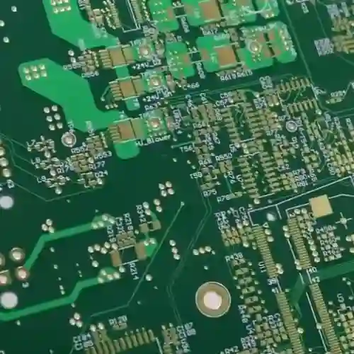
Every time I see those complex PCB design drawings, I can’t help but laugh. Some people treat high-speed circuit board design like solving a rigorous mathematical problem. But after actually working on a few designs, you’ll find that those theoretical rules and regulations aren’t nearly as rigid in practice.
When I first started working with high-speed PCBs, I also blindly followed various calculation formulas. Later, I realized that it’s better to focus on getting the critical lines routed first than to obsess over theoretically perfect layering. Once, a communication board I designed had signal interference during testing. Everyone thought the layering scheme was the problem, but adjusting the layout of key components solved the issue.
Now, I find the discussions about each layer having to have a fixed function quite amusing. The vitality of a circuit board lies in its flexibility; sometimes interleaving power and signal layers can solve unexpected problems. Of course, this requires an intuitive understanding of current flow.
I remember once, to meet a deadline, I placed the RF module directly next to the regular digital signal layer. My colleagues thought it was too risky. But through clever grounding and isolation, the final test results were even better than the standard design. This case made me realize that PCB design is more like artistic creation than mechanically following specifications.
Regarding routing density, my experience is that it’s better to reserve extra space than to over-compress. I’ve seen too many designs that are impossible to modify later because of the pursuit of miniaturization. Those densely packed lines are like paintings without negative space, losing room for adjustment and increasing the probability of failure.
The most frustrating thing is seeing newcomers blindly applying design specifications from large manufacturers. They always think that replicating successful cases will guarantee success, but they ignore the unique characteristics of their own projects. It’s like wearing someone else’s perfectly fitting clothes – it might not suit you. Every circuit board should have its own unique soul.
I’m now more focused on how to design for future evolution. For example, reserving several switchable partitions in the power layer or preparing alternative paths for high-speed signal lines. This flexible thinking is far more practical than rigidly adhering to layering theories, because the iteration speed of electronic products far exceeds our imagination.
Sometimes, simple and straightforward methods are more effective. There was a project that used the most basic 4-layer board structure, and by optimizing component placement, it still achieved gigabit-level transmission. This made me reconsider whether those so-called high-end designs are truly necessary.
Ultimately, good PCB design should be as natural as breathing; you shouldn’t deliberately pursue theoretical perfection. More importantly, you need to cultivate a sensitivity to current flow in practical operation – this kind of experience can’t be learned just from books.
I always feel that many people overcomplicate high-speed PCBs. In the end, it’s more about balance – the signal needs to travel fast and stably, while the entire system needs to be adequately powered. You might find that sometimes severe signal jitter isn’t caused by crosstalk, but rather by insufficient power supply. At this point, you need to look back and see if your power distribution is even, and if any chips in any corner are “starving.”
I remember once debugging a board; the routing was done according to specifications with equal length matching, but the eye diagram still wouldn’t open. After much effort, I discovered that there was a gap in the power plane, causing unstable voltage in a certain area. Later, I redesigned the layering structure, bringing the ground plane and power plane closer together, and the problem was solved. This made me realize that just focusing on the signal path is not enough.
The most easily overlooked aspect of PCB layout is the current return path. Many people only care about how the signal lines run when designing a board, but they forget that current, like water, always needs to find a way back. If the ground plane is fragmented, the signal may be overwhelmed by noise even if the routing is perfect. I usually keep a complete ground plane under critical signals; sometimes I’d rather add more vias to ensure a smooth return path.
Speaking of power integrity, it’s actually a very practical problem – as simple as building gas stations on a highway. You need to ensure that every chip gets clean and stable energy immediately when it needs it. Some engineers like to pile on capacitors, but more capacitors aren’t always better; placing them incorrectly can actually introduce resonance. I usually simulate the PDN impedance first, find the weak points in the frequency domain, and then reinforce them accordingly.
The biggest fear in high-speed design is treating the symptoms instead of the root cause. I once saw someone revise their routing several times to improve signal integrity, only to find the problem was actually due to power supply ripple. So now, whenever I encounter timing issues, I always check the power supply quality first. After all, how can a chip run at high speed on an empty stomach? It’s like asking an athlete to run a marathon on an empty stomach – even the best track is useless.
Sometimes I feel that designing high-speed PCBs is more like playing a delicate balancing game: the signals need to be fast but not unstable, and the power supply needs to be stable but not bulky. You have to constantly make trade-offs between speed, noise, and power consumption; there are no absolutely correct answers, only compromise solutions that are best suited to the current situation. This is probably what makes it both frustrating and fascinating – you can always find new areas for optimization in the details.
Every time I see articles that make high-speed PCB routing sound incredibly mysterious, I want to laugh. It’s as if you have to use a bunch of technical jargon to sound knowledgeable. When I first started in this field, I was also confused – I always wanted to cram everything into the smallest possible space.
Later, I realized that you can’t be too rigid about this.
Once, I helped a friend modify a board. He had crammed all the high-speed components together, thinking it would shorten the trace lengths, but the signals interfered with each other terribly. I tried slightly separating a few key components, and that solved the problem.
The essence of routing is actually finding a balance point.
You have to consider how the signal travels most comfortably, not simply pursue the shortest path. For example, for high-speed signal lines like PCIe, a slight curve might be better than a straight line; the key is to control impedance continuity. Specifically, when a signal propagates through a transmission line, any impedance discontinuity will cause reflections, damaging signal integrity. Therefore, avoid 90-degree right-angle turns in routing, use 45-degree or curved traces, and maintain a complete reference plane. For differential signals, ensure equal length matching between the pairs, and the length deviation should be controlled within the timing tolerance. I’ve seen too many people dive straight into drawing traces only to end up completely overwhelmed by revisions later.
A better approach is to spend time planning the overall layout, separating sensitive signals from ordinary lines. For example, clock signals and high-speed data lines should be kept far away from noise sources such as switching power supplies and crystal oscillators, and shielding ground lines should be added for isolation if necessary. At the same time, power supply areas of different voltage levels should be clearly demarcated to avoid cross-interference.
Sometimes, it’s perfectly normal to completely redesign the layout to create clean space for critical signals.
The power supply section is often overlooked, but its stability directly affects signal quality. Power supply noise can affect signal edges through common-mode coupling, leading to timing shifts. A reasonable decoupling capacitor layout is crucial—high-frequency small capacitors should be placed close to the component pins, while low-frequency large capacitors should be distributed around the periphery of the power supply area. When splitting power planes, care should be taken to avoid creating narrow gaps, as this will increase loop inductance.
I remember one project that took a long time to debug, only to discover that excessive power supply ripple was causing signal jitter; the problem was only solved after redesigning the power plane.
Now, when I design, I plan the power and ground lines first before handling the signal section, and I find it much more efficient. A complete ground plane not only provides a stable reference potential but also acts as electromagnetic shielding. In multi-layer board design, it is recommended to use an interleaved stacking method of ground layers and signal layers to effectively control crosstalk.
Regarding vias, my opinion might be unconventional—there’s no need to be overly afraid of them.
Of course, you shouldn’t overuse them, but you should use them when necessary; the key is to control the quantity and quality. Vias introduce parasitic capacitance and inductance; for GHz-level signals, each via can introduce a delay of 0.3-0.5 ps. However, by using back-drilling technology to remove via stubs, or by using micro-via arrays, their impact can be minimized. When changing layers for important signal lines, it’s best to add ground vias around the vias to form a shielding structure.
Once, to avoid a sensitive area, I added two vias to a high-speed line; my colleagues said it wouldn’t work, but the tests showed it met all the requirements.
Simulation tools are useful, but you can’t rely on them completely. For example, transmission line loss models may not accurately simulate the dielectric inhomogeneity of the board material, and chip IBIS models often deviate from actual measurements. It is recommended to reserve test points on critical links and use a vector network analyzer to measure S-parameters to verify the simulation results.
I trust actual test data more because simulation models always have idealized aspects, while the real environment is much more complex.
It’s best to develop the habit of checking as you go, rather than waiting until the end to verify. You can utilize the real-time DRC function of the routing software, setting rules for line width, spacing, and length matching. Perform local simulations after every 10% progress to promptly identify and correct problems such as reflections and crosstalk.
Some designers now rely too much on simulation software and forget the importance of actual testing. Simulation can tell you the performance under ideal conditions, but in actual prototyping, board material tolerances and manufacturing precision can lead to unexpected results. I always leave a few test points near critical networks, even if it means using a little more board space; it’s worth it. For example, by reserving SMA connectors next to the differential pair, the S-parameters can be directly measured using a vector network analyzer, which helps in identifying discrepancies between the simulation and the actual measurements.
Ultimately, high-speed PCB design is a process that requires continuous adjustment; there is no one-size-fits-all formula. Every time you encounter a new problem, it’s an opportunity to learn. As long as you remain patient and try a few times, you will always find a working method that suits you.
Over the years of working on high-speed boards, I’ve had a particularly profound realization—many people get bogged down in formulas and calculating impedance values, which is quite time-consuming. I remember once helping a friend with a board; he was arguing with me about various theoretical data, insisting that the stripline width had to be controlled at 5.2 mils. However, when the actual prototype came back, the signal eye diagram was distorted. We then reran the simulation using a field solver and discovered the problem was that the reference plane on the adjacent layer was too fragmented.
In fact, what truly affects signal quality is often not those micron-level width deviations, but the overall routing path planning. For example, once we arranged the DDR chips around the main chip in a fan shape, and no matter how we routed the clock lines, we couldn’t avoid reflections. We ended up completely redesigning it, moving all the memory modules to the back of the board and connecting them directly through blind vias, which eliminated most of the serpentine traces.
Now, when I encounter a new project, I usually start by opening the layer stack manager, setting the copper thickness and dielectric parameters, and letting the solver automatically calculate the possible line width range. This is much faster than manual trial and error, especially when routing differential pairs. Sometimes, slightly increasing the spacing is more effective than striving for perfect symmetry.
There’s also a small detail that’s easy to overlook—it might not matter for low-speed boards, but for high-speed signals, impedance discontinuities are more critical than absolute errors. For example, areas with dense vias can easily form resonance points. In this case, instead of desperately trying to suppress single-ended impedance, it’s better to avoid sensitive areas during the routing stage. Ultimately, software tools can only help you calculate numerical values; true layout expertise comes from practical experience. It’s like building with LEGOs: you need to understand the overall structure first before filling in the details. Otherwise, even if every connection conforms to theoretical values, the entire board might fail due to unnecessarily long signal paths.
In my years of high-speed PCB design, I’ve noticed an interesting phenomenon – many people immediately focus on the data in the material specifications. Actually, instead of agonizing over whether to use top-tier materials to reduce the tangent loss by a few hundredths of a percent, it’s better to first understand one thing: how far does your signal actually need to travel? I’ve seen too many engineers cramming PTFE material into palm-sized boards, resulting in a threefold increase in cost with minimal performance improvement.
I remember once helping a client revise a design; their original stack-up used six layers, all to create space for BGA fan-out. In reality, optimizing the power plane allowed them to achieve the same result with only four layers. The key was increasing the spacing between adjacent signal layers to control impedance, which was more effective than simply adding more layers. Sometimes, the simplest solution is the most reliable.
Regarding material selection, I’m quite pragmatic. Ordinary FR4 is perfectly sufficient for small digital circuits unless your board needs to handle millimeter waves or the traces are long enough to wrap around a conference room. And don’t forget, the material is only one influencing factor; the geometry of your traces is equally important – even with the most expensive low-loss materials, right-angle bends can still completely ruin the signal.
For impedance control, my approach is to first draw a preliminary stack-up sketch and then immediately communicate with the manufacturer. They often advise on which thickness combinations are easier to manufacture or recommend more cost-effective alternatives. Once, I designed a board with an HDMI interface, and after calculating the impedance myself, I was quite confident. However, the manufacturer suggested increasing the dielectric layer thickness by 0.1 millimeters, which reduced the cost by 15%, and the final product had better impedance matching.
In fact, the biggest pitfall in high-speed design is working in isolation, especially during the stack-up planning stage. Early communication with the manufacturer can save 80% of the trouble later on, as they have seen thousands of boards and know which laminates are most stable in mass production. As for calculation tools, field solvers are accurate, but for conventional digital circuits, using online impedance calculators for quick iterations is often more efficient. Finally, I want to say, don’t overcomplicate high-speed design. Often, the problem isn’t the materials, but rather the layout failing to provide enough breathing room for sensitive signals. For example, squeezing clock lines next to a switching power supply will inevitably lead to interference, no matter how low-loss the substrate is.
Every time I see someone talking about high-speed PCBs in a mystical way, I want to laugh. Simply put, it’s just about creating a good path for the signal. I worked on a board with 25G signal lines next to a switching power supply. Initially, everyone thought it was doomed, but I cleaned up the reference plane and ensured sufficient spacing, and the resulting eye diagram was even better than some boards specifically designed for isolation. For example, when handling the reference plane, I paid particular attention to avoiding power plane splits under critical signals, ensuring a continuous and complete return path. This effectively suppressed high-frequency noise even when adjacent to the switching power supply.
Many people think of high-speed design as simply adding layers and using expensive materials, but the most important thing is the fundamentals. I’ve seen people spend a fortune on special board materials but make basic mistakes in power plane splitting, leading to an unstable system. What’s truly important is understanding how the current flows back, not blindly pursuing so-called advanced technologies. For example, in multilayer board design, even using standard FR4 material, ensuring that the power and ground planes are closely coupled can achieve low impedance power delivery, which is far more practical than stacking expensive dielectric materials.
The term “impedance control” is often made to sound too mysterious; it’s simply about preventing signals from bouncing around randomly. During a board revision, I found that simply moving the vias a few millimeters away from critical traces significantly improved reflections. This kind of fine-tuning is much more practical than changing materials, especially considering cost constraints in mass production. Specifically, vias generate parasitic capacitance and inductance, and when they are too close to high-speed lines, they create impedance discontinuities. Simple layout adjustments can mitigate this effect without changing the stackup or materials.
The loss factor becomes a critical flaw, like using ordinary scissors to cut a precise circuit pattern—it’s not that the tool itself is faulty, but rather that it’s mismatched.
Once, while visiting a car radar production line, I noticed they specifically chose special laminates even for the antenna substrates. The engineers said that although the cost was 30% higher than FR4, the signal fidelity directly affects detection accuracy, and this is not something they can compromise on.
Now, when I see young designers immediately diving into drawing schematics, I always ask about the operating frequency range. Some projects clearly involve high frequencies, yet they’re still using standard FR4 PCBs. This is like putting bicycle tires on a sports car—it can still run, but it simply won’t perform as it should.
The choice of materials is fundamentally about respecting physical properties. FR4 is like reliable work boots, suitable for everyday commuting, but for rock climbing, you need professional climbing boots.
While renovating my old house recently, I found a radio from the 1980s. When I opened it and saw the yellowed circuit board inside, I suddenly realized that we’re always pursuing the latest technology, but we’ve overlooked the logic behind material evolution.
Many people think that the transition from paper-based substrates to fiberglass is an inevitable trend, but I think it’s more like an accident. An old factory foreman once told me that early substrates made of compressed cotton paper, although prone to moisture and deformation, were actually more stable than some modern materials in a humidity-controlled laboratory.
Once, I helped a friend repair an old oscilloscope and found that it used an FR3 substrate. This material is rarely seen now, but its unique woven fiberglass structure results in particularly uniform signal attenuation. In contrast, the currently popular FR4, while having impressive specifications, often exhibits signal distortion at the edges in practical applications.
I remember visiting a production line that still used old equipment. Their quality control manager had an interesting point of view: newer PCB models aren’t necessarily suitable for all scenarios. For example, the dielectric constant fluctuations of FR4 boards in high-frequency environments can affect the readings of precision instruments. They still insist on using custom substrates in certain processes, not out of conservatism, but based on actual testing.
The most exaggerated example I’ve seen is a research unit that ordered a batch of ceramic substrates, but the mismatch in thermal expansion coefficients led to the entire batch of equipment being scrapped. In fact, in many cases, ordinary epoxy resin PCBs can avoid these problems.
Now, the industry is constantly talking about fifth-generation materials, but what truly determines the lifespan of a circuit board is often the fundamental manufacturing process. Once, I plugged in a radio from thirty years ago, and the circuit board, covered in oxidation spots, still worked perfectly—material advancements are important, but choosing the right materials for the right application is key.
Ultimately, choosing a circuit board is like choosing shoes: more expensive isn’t always better; it depends on where you’re going. Next time you design a circuit, ask yourself: does this project really need top-of-the-line materials? Perhaps a standard-grade PCB is the optimal solution.
When selecting components for a security monitoring system, most attention goes to
Behind the mobile signals we rely on daily lies the sophisticated engineering
Many assume that wireless communication PCBs require expensive high-frequency materials. This guide
- 중소규모 배치 생산 전문가
- 고정밀 PCB 제작 및 자동화된 조립
- OEM/ODM 전자 프로젝트를 위한 신뢰할 수 있는 파트너
영업 시간: (월~토) 9:00~18:30