
Why the Circuit Board Beneath the Camera Determines Whether Your Surveillance System Holds Up for Years
When selecting components for a security monitoring system, most attention goes to
I recently noticed a rather interesting phenomenon. Many people think of rigid-flex PCBs as a new technology, but in fact, it has been around for decades. What truly caught my attention are the changes brought about by materials science, especially the application of materials like graphite in rigid-flex circuit boards.
I remember visiting an electronics manufacturing exhibition last year and seeing a sample displayed by a manufacturer. They used a special graphite composite material, which supposedly allows the circuit board to maintain better stability during repeated bending. This reminded me of the early rigid-flex boards that were prone to failure at the bending points; the progress made is indeed significant.
However, I think many people’s understanding of rigid-flex technology is still superficial. For example, the through-hole design is a detail that significantly impacts overall performance. Some engineers design the through-holes too densely to save space, which actually affects reliability. I saw a case where an unreasonable through-hole layout led to connection problems in the entire module after only a few months of use.
Speaking of material selection, I’ve noticed a misconception in the industry. Many people think that newer materials are always better, but in reality, the actual application scenario must be considered. For example, in some high-temperature environments, traditional rigid-flex PCBs are more stable than versions using the latest materials. It’s like choosing clothes; you can’t just look at the style, you also have to consider whether it’s suitable for the occasion.
A recent project gave me a deeper understanding of this issue. We tested different ratios of rigid and flexible materials and found that more rigid material isn’t always better. Sometimes, appropriately increasing the proportion of flexible areas can actually improve overall performance. This made me realize that designing rigid-flexible circuit boards requires a more flexible mindset.
I’ve noticed that some manufacturers are starting to experiment with combining graphite materials with other composite materials. Although I can’t disclose specific data, this approach has indeed led to performance improvements. However, this innovation also requires supporting processes, such as more precise operations in through-hole processing.
The longer I work in this field, the more I realize that designing rigid-flexible PCBs is like cooking – you can’t just pile the best ingredients together to make a delicious dish. You need to consider the compatibility of various materials and the feasibility of the manufacturing process. Sometimes the simplest solution is the most effective.
Speaking of future trends, I think the focus shouldn’t be on pursuing a certain percentage of performance improvement.
I recently discovered that many people’s understanding of rigid-flexible circuit boards is still superficial. The real charm of these products lies in their ability to break the limitations of traditional circuit design. I remember helping a friend modify a drone once and found the internal wiring was incredibly messy. After redesigning it with a rigid-flexible PCB, the entire device became more than a third lighter.
A friend who works in medical devices told me about the challenges in their industry. Some equipment needs to perform complex functions in a limited space, and this is where the advantages of rigid-flexible PCBs become apparent. Traditional circuit boards take up too much space, while purely flexible boards lack support points. When upgrading endoscopes, they specifically made the critical parts rigid while keeping other parts flexible.
Once, while visiting an electronics factory, I saw workers repeatedly adjusting the wiring positions when assembling smartwatches. If they had used a rigid-flexible design, they could have saved a lot of trouble. Although the cost of the board material itself might be higher, the overall cost would be more economical.
The most ingenious application I’ve seen is in automotive navigation systems. The space behind the dashboard is very tight, so the designers made the main board into several rigid sections connected by flexible circuits. This ensured the stability of the core components while solving the wiring problem.
Many people think that the manufacturing process for these boards is complex and are hesitant to try them. However, domestic manufacturers now have very mature technology; the key is to find the right partner. For a project requiring high-temperature resistant materials, the manufacturer recommended a special polyimide substrate, and the results were unexpectedly good.
The demand for rigid-flexible circuit boards in the wearable device field is becoming increasingly evident. The wristband of a smart bracelet requires a flexible circuit board, while the watch face needs rigid support. This inherent combination of requirements perfectly matches the characteristics of the materials used.
Some engineers worry about the connection between the rigid and flexible parts, but current technology can achieve a smooth transition. The key is to control the bending radius. I’ve seen some products where this detail was handled poorly, leading to frequent malfunctions later on.
The aerospace industry has even higher requirements for these types of circuit boards, needing to ensure both stable signal transmission and adaptability to complex environments. I previously worked on the design of satellite communication equipment, and they even had to consider the impact of thermal expansion and contraction on the circuitry.
I believe that flexible-rigid combination technology will become increasingly common in the future, especially as electronic products become smaller. The limitations of traditional circuit boards will become more apparent, and sometimes innovation starts with simply changing the materials.
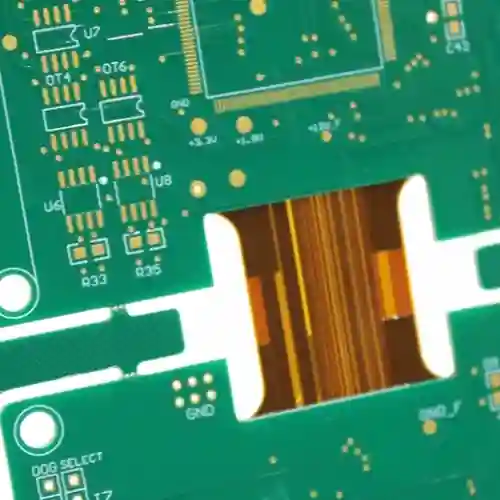
I’ve recently been thinking a lot about the inconspicuous connecting parts in electronic devices. I used to think of circuit boards as just rigid green boards, but then I discovered there are so many variations. The connecting methods that can maintain their shape while still being flexible are particularly interesting.
I remember once disassembling an old mobile phone and noticing how cleverly the flexible connecting part between the motherboard and the screen was designed. It wasn’t as prone to breaking as traditional wires, nor as fragile as flexible flat cables. This design made me realize that the lifespan of many electronic products depends on these details. For example, wearable devices are bent thousands of times every day, and ordinary connection methods simply can’t withstand that.
Once, I helped a friend repair a drone and encountered a similar problem. The connection between the flight control board and the camera module had loosened due to vibration, causing unstable video transmission. We only solved the problem completely after switching to a more reliable connection solution. This experience made me realize how important it is to use appropriate connection methods between moving parts.
Many smartwatches now use a similar design approach. The watch face needs to remain rigid to protect the components, while the strap needs to be flexible enough to adapt to the wrist. This seemingly contradictory requirement perfectly illustrates the wisdom of good design. Good products aren’t simply a collection of technologies, but rather a balance between various needs.
I’ve noticed that the medical device field has even higher requirements for this type of technology. For example, the probe of an endoscope needs to ensure image transmission quality while also being able to move flexibly within the human body. This makes me think that technological advancements are often hidden in these unseen details. Sometimes the most crucial breakthrough isn’t about how flashy the features are, but how to make different parts work together better. In fact, many innovations in life stem from resolving contradictions. Just like expansion joints in buildings, which ensure structural stability while allowing for thermal expansion and contraction, the same principle applies to electronic devices. Finding the optimal balance between stability and flexibility is where the true test of design skill lies.
When selecting components for a security monitoring system, most attention goes to
Behind the mobile signals we rely on daily lies the sophisticated engineering
Many assume that wireless communication PCBs require expensive high-frequency materials. This guide
- 중소규모 배치 생산 전문가
- 고정밀 PCB 제작 및 자동화된 조립
- OEM/ODM 전자 프로젝트를 위한 신뢰할 수 있는 파트너
영업 시간: (월~토) 9:00~18:30