
From Novice to Expert: Sharing My Experience in Pin Header PCB Selection
As an electronics enthusiast, I’ve come to understand firsthand the impact of
I’ve always found working with metal substrates quite interesting. When I first started PCB design, I was always focused on improving heat dissipation, but later I discovered that choosing the right metal substrate is actually quite important.
I remember once using an aluminum substrate for a heatsink in a project, and finding that surface treatment was particularly critical. If the temperature parameters weren’t properly controlled during the etching process, edge burrs could easily appear.
In fact, many engineers now prefer to use traditional FR4 material for circuit board design. However, in high-power scenarios, ordinary board materials simply cannot withstand the heat buildup. This is where metal substrate PCBs come in.
I prefer to include sufficient heat dissipation margin in my designs. For example, when designing an LED driver module, I specifically increased the copper layer thickness to 2 ounces. Although the cost is higher, the long-term operational stability is significantly improved.
Sometimes, engineering feels like playing a balancing act. You have to consider performance, control costs, and ensure reliability. This is especially true when dealing with metallic materials, where you have to be careful about the coefficient of thermal expansion.
Recently, I’ve been trying a new surface treatment process and found the results quite good. However, the specific details need further verification to determine if it’s suitable for mass production.
While working on an industrial power supply project, I discovered an interesting phenomenon—I initially thought the heat dissipation problem could be solved simply by adding a fan. However, during testing, the circuit board got so hot you could fry an egg on it, realizing it wasn’t that simple. Further analysis revealed a serious flaw in the heat dissipation path design; there was a significant thermal resistance bottleneck between the heat source and the heatsink, and simply increasing the airflow speed wouldn’t solve the fundamental problem.
That experience made me seriously research the application scenarios of metal substrate PCBs. Many people think that this type of board is mainly used in the military and aerospace fields. In fact, even smart home devices are now quietly using metal substrates—for example, security cameras that need to operate for long periods of time. If the heat generated by the internal processor working continuously cannot be dissipated, the image sensor will start to show noise. This thermal noise phenomenon is particularly noticeable in 4K high-definition cameras, causing snow-like interference in the image.
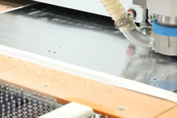
When choosing a PCB supplier, I particularly value their ability to handle details. Once, during a factory visit, I saw them using lasers to cut aluminum substrates. The cuts were so smooth, as if they had been polished. This level of craftsmanship directly affects the stability of the final product. The ultraviolet laser they use can achieve micron-level processing precision, ensuring that the thermal interface does not have gaps due to burrs.
I remember a supplier showing me their comparative test: under the same power conditions, the temperature curve of ordinary FR4 board rose like a slope, while the metal substrate remained almost horizontal. Test data shows that at an ambient temperature of 40℃, the junction temperature of the chip on the FR4 board exceeded 125℃ within half an hour, while the metal substrate remained stable below 85℃.
Now, for designs requiring high current, I prioritize using a partial metal substrate solution in the power module section. For example, in a DC-DC converter, the power MOSFET is directly mounted on an aluminum substrate, with thermal pads ensuring close contact with the casing. This reduces thermal resistance to about 1/5 of traditional solutions.
Recently, a friend who works on automotive equipment complained to me that his product kept restarting in high-temperature environments. The problem was solved after replacing the ordinary board material under the main control chip with a metal substrate with thermally conductive adhesive. After the modification, the chip surface temperature decreased by nearly 30℃ during continuous operation at an ambient temperature of 85℃.
Actually, there’s a very intuitive way to judge a supplier’s reliability—see if they can clearly explain the applicable scenarios for different metal substrate materials. For example, aluminum substrates are suitable for most general applications, copper substrates are more suitable for extreme high-current situations, while iron substrates perform exceptionally well in applications requiring electromagnetic shielding.
In a previous project, we needed to achieve 20A current transmission within a limited space. We experimented with three different copper substrate thicknesses to find the optimal balance between heat dissipation and mechanical strength. Ultimately, we chose a 2.0mm thick substrate, ensuring sufficient current carrying capacity while avoiding the reduced soldering yield caused by excessively thick substrates.
Sometimes, choosing a substrate is like getting eyeglasses; you have to try them on to know if they fit. Just looking at the specifications doesn’t give you a real sense of the difference. For example, two aluminum substrates with the same thermal conductivity can have different heat dissipation effects by more than 15% due to different surface treatments.
I usually have suppliers provide small-batch trial production samples before starting a new project. Soldering a few prototypes and testing the thermal conductivity is more effective than reading countless technical documents. Recently, I discovered a detail during testing: for the same specifications of metal substrates, the thermal resistance values provided by different suppliers could vary by as much as 20%, which directly affects the accuracy of heat dissipation design.
In the past two years, I’ve noticed a trend: more and more consumer electronics products are adopting hybrid structures in certain critical areas—for example, fast charging heads for mobile phones use both ordinary FR4 substrates and embedded metal cores in areas with high heat generation. This localized enhanced heat dissipation design controls costs while precisely addressing hotspot issues.
Reliable suppliers proactively remind you of design details. Once, their engineer specifically called to say the location of the heat dissipation holes on my drawings needed adjustment to avoid stress concentration areas—this level of professionalism is reassuring. They even provided a thermal simulation report showing a more uniform thermal stress distribution on the substrate after the adjustment.
Recently, I tried using a metal substrate in an LED driver circuit, and the results were surprisingly good. Although the thermal conductivity is not as high as aluminum, the magnetic shielding properties actually solved the problem of interference from adjacent circuits. It seems that material selection really cannot be based on a single indicator. After forming effective magnetic shielding around the driver IC, the interference of switching noise on sensitive signal lines was reduced by more than 40dB.
I always find it laughable to see those advertisements that mythologize metal substrates. It’s just a tool; its value lies in its correct application. The key is to make judgments based on the actual application scenario. For example, forcing a metal substrate into a low-frequency, low-power circuit not only increases costs but may also lead to soldering reliability issues due to CTE mismatch.
I’ve recently noticed a rather interesting phenomenon—more and more electronic products are now using metal substrates for their PCBs. This reminds me of a situation I encountered last year when helping a friend upgrade his car audio system. His car amplifier kept overheating and shutting down. We tried various cooling fans, but the results were unsatisfactory. The problem was solved after switching to an aluminum substrate.
In fact, this design is particularly suitable for equipment operating in high-temperature environments. I remember visiting a factory once and seeing that the robotic arm controllers on the automated production line used metal substrates. The engineers told me that these devices need to operate 24/7, and ordinary FR4 boards simply cannot withstand the continuous high temperatures. The metal substrate acts like a natural heat sink for the circuitry, allowing heat to be quickly conducted to the entire board surface.
Speaking of power supply equipment, a friend of mine who works in charging pile R&D shared their experience. High-power fast charging modules generate tremendous heat during operation. After testing different solutions, they found that using a copper substrate PCB could reduce the temperature of key components by more than 20 degrees Celsius. This not only improves charging efficiency but also significantly extends the lifespan of the equipment.
However, metal substrates are not a panacea. I’ve seen some designers, in pursuit of better heat dissipation, place all the circuitry on a metal substrate, resulting in signal interference problems. Later, they switched to a hybrid design—using a metal substrate for the power section and traditional materials for the signal processing section. This solved both heat dissipation and signal integrity.
Now, even home appliances are starting to try this design. My new air purifier uses an aluminum substrate to drive the LED indicator lights. Although it’s a small detail, it’s definitely more durable than ordinary circuit boards.
I think we’ll see more innovative applications in the future. For example, wearable devices using flexible metal substrates can ensure heat dissipation while adapting to the human body’s curves. However, achieving this goal requires solving the problems of metal material flexibility and cost.
Every time I see these innovative applications, I’m amazed at how much knowledge lies behind seemingly simple material choices. Choosing the right PCB material is as important as finding the right living environment for your circuitry—it needs to be comfortable, safe, and durable.
Perhaps this is the charm of engineering design; profound wisdom is always hidden in seemingly simple choices.
I’ve always felt that articles discussing metal substrate PCBs focus too much on technical parameters. Yes, we all know they have good heat dissipation and are suitable for high-power applications, but this is only the most superficial understanding.
What truly interests me is the resilience these boards exhibit in practical applications. Ordinary FR4 material is prone to deformation at high temperatures, but the metal substrate provides structural support—this isn’t just a matter of heat dissipation, but rather a matter of long-term product stability.
I remember once testing an outdoor lighting device using an aluminum substrate at nearly 60 degrees Celsius. Ordinary boards would have warped long ago, but these boards with metal substrates withstood a continuous 72-hour aging test.
Many people focus on the thickness of the insulation layer, but I’m more concerned with its uniformity. Once, a supplier provided a sample with a local dielectric layer thickness deviation exceeding 10%, which directly caused solder joint cracking under large temperature differences.
There’s a reason why more and more power modules are adopting this structure. The metal substrate acts like a heat dissipation framework for the circuitry, distributing thermal stress and providing mechanical protection.
The most ingenious application I’ve seen is in automotive electronics. They directly mount power devices onto a metal substrate and use the entire car body as a heat sink—a far more sophisticated approach than simply adding heat sinks.
Sometimes I wonder why the adoption of this type of substrate isn’t as rapid. Perhaps people are still deterred by the initial cost, but considering the ongoing maintenance expenses, its cost-effectiveness is actually quite outstanding.
Recently, I’ve seen some manufacturers experimenting with adding special fillers to the insulation layer, and the effect is indeed significantly improved. However, this also increases the difficulty of the process, which is a balance worth noting.
Ultimately, choosing the right substrate is never simply a technical issue; it’s more about considering the overall product lifecycle. Metal substrates offer not only heat dissipation advantages but also design freedom—the confidence that this board can withstand more demanding operating conditions is valuable in itself.
I recently re-examined the choice of metal substrates while considering a project. Many people instinctively think these substrates are ridiculously expensive and immediately give up, which is a bit of a pity.
I remember last year, a client for an LED lighting project initially insisted on using the cheapest ordinary substrate, but heat dissipation problems occurred during the sample stage. Switching to an aluminum substrate actually reduced the overall cost because it eliminated the need for additional heat sinks.
The true value of metal substrates lies in their ability to solve thermal management problems that ordinary PCBs cannot handle, especially in applications with dense power devices. The savings in external heat dissipation costs and space often far outweigh the price difference in the substrate itself. Of course, this requires specific calculations and isn’t always worthwhile.
Regarding certifications, I’ve learned my lesson the hard way. Once, for a medical device project, the manufacturer could produce metal substrates but lacked ISO 13485 certification, causing the entire product certification process to stall. Now, I prioritize verifying whether a manufacturer has industry-specific certifications; this is more important than technical specifications.
Speaking of fine-grained circuitry, it’s not uncommon for mainstream manufacturers to achieve 3-4 mils. However, the real test of skill lies in the stability during mass production. I prefer manufacturers with slightly lower circuit precision but reliable quality control, as engineering samples and mass production are two different things.
Actually, the biggest headache with metal substrates isn’t the unit price, but the lack of design flexibility. For example, if vias are to be included, insulation processing is subject to many limitations. Sometimes, to avoid these limitations, the layout needs significant changes, requiring a careful consideration of whether it’s absolutely necessary.
Some manufacturers are now offering early design support, which is quite important. They are familiar with process bottlenecks and can identify hidden issues like thermal expansion coefficient matching in advance, which is much better than us struggling and having to rework everything ourselves.
Ultimately, choosing a metal substrate is like choosing materials for home renovation. You can’t just look at the unit price; you have to consider the hidden benefits and limitations it brings. Sometimes, spending a little more on the substrate can actually save more at the system level—that’s the smart approach.
I’ve always felt that many people have a misconception about metal substrates—they always think that choosing a thick aluminum or copper plate will solve the heat dissipation problem. In reality, what truly hinders heat conduction is often that thin insulating layer. Think about it: heat travels from the chip to the copper foil and then downwards, only to be trapped in this layer, less than a hair’s breadth thick—how frustrating!
I’ve seen many engineers spend a lot of money choosing high thermal conductivity metal substrates, only to find that the overall heat dissipation effect is worse than ordinary FR4 substrates because the insulation material wasn’t chosen correctly. Once, a test comparing two insulating coatings with different thermal conductivity, even with the same aluminum substrate, showed a temperature difference of more than ten degrees Celsius. This thing is like a water pipe; a very narrow section in the middle restricts the flow of the entire pipe.
Currently, the high-performance metal substrates on the market are actually competing on technological breakthroughs in the insulation layer. Some manufacturers use ceramic-filled epoxy resin with a thermal conductivity exceeding 3 W/m·K, while traditional materials may not even reach 1. Although the numerical difference may seem small, in practical applications, it can directly double the lifespan of components.
Of course, thickness is also a point that needs to be weighed. Too thick, and while the voltage resistance is indeed better, heat transfer becomes more difficult; too thin, and there’s a risk of short circuits. I generally advise customers to first clarify the operating environment of the equipment—for industrial equipment operating under high loads for extended periods, it’s better to sacrifice some heat dissipation to ensure insulation reliability, as safety is always the top priority.
Recently, I’ve also noticed an interesting phenomenon: some manufacturers are starting to experiment with the insulation layer, such as creating a gradient thermal conductivity structure, using high thermal conductivity materials near the chip and materials with higher voltage resistance at the bottom. This approach is quite ingenious.
Ultimately, when choosing a metal substrate, you can’t just focus on the metal part; the unassuming insulation layer is the real game-changer. Next time you’re designing, consider asking your suppliers about the specific formula of their insulation materials.
I’ve been thinking a lot about metal-based circuit boards lately, and it’s quite interesting. Many people think choosing materials is as simple as looking at thermal conductivity—but it’s not that simple.
I remember an engineer once showing me a sample and asking why a copper substrate was damaging the chip. Upon disassembly, we discovered the problem was with the insulation layer: the supplier, trying to save costs, used cheap resin, resulting in double the thermal resistance. This made me realize that the entire heat dissipation path is like a water pipe system; the metal substrate is just the main pipe, and if a small valve gets stuck at the connection, even the thickest pipe is useless.
The industry is currently touting all-copper solutions, but I believe an aluminum substrate paired with a high-performance insulating layer is a smarter choice, especially for vibration-sensitive devices. During our last test of an automotive headlight module, we found that the weight of the copper substrate caused fatigue fracture at the solder joints, while the aluminum substrate with a resilient copper pillar structure passed the 200-hour vibration test.
While electroplating can indeed create a perfect one-piece molded copper pillar structure, the cost can deter many customers. We tried a modified etching method—leaving a 0.1 mm expansion gap during the lamination of the insulation layer and then filling it with conductive adhesive—and the results were surprisingly good. This is like allowing some breathing space for thermal expansion, controlling costs and avoiding the risk of cracking.
One industrial inverter customer insisted on using the thickest copper substrate, but the heat dissipation wasn’t significantly improved. During assembly on the production line, the excessive weight of the substrate damaged several connectors. Later, switching to an aluminum substrate with a reinforced frame resulted in an 18% improvement in overall heat dissipation efficiency. Sometimes, the optimal solution lies in the overall system design, not just the highest performance of a single parameter.
The real test for metal substrates is extreme temperature cycling. The most successful case I’ve seen is a clever design in aerospace controllers—making the copper pillars into a honeycomb structure, which reduced weight and evenly distributed thermal stress. This approach is far superior to simply piling on materials.
Ultimately, choosing a metal substrate is like choosing clothes—it’s not about wearing the most expensive pieces. It’s about considering the overall application scenario. Sometimes, saving on the cost of a copper substrate and using the money to upgrade the insulation or optimize the structure can yield surprisingly good results.
I’ve seen too many engineers struggle after cramming ordinary PCBs into high-power devices. Last year, an industrial power supply customer insisted on using a fiberglass board to mount a high-power MOSFET, resulting in the burnt-out of the third prototype before they came to us. By then, the aluminum substrate was so hot it could fry an egg, but the chip temperature was managed to stay below 85 degrees Celsius.
What fascinates me most about metal substrates is their honesty. The temperature you feel is the actual temperature of the component, unlike some fiberglass boards that appear cool on the surface but harbor a hidden furnace underneath. This straightforward heat dissipation characteristic is particularly suitable for scenarios requiring long-term full-load operation, such as electric vehicle charging stations or stage lighting equipment.
Some people believe that metal substrates cause electromagnetic interference problems, but the opposite is true. We’ve conducted tests showing that in motor driver applications, aluminum substrates actually suppress high-frequency noise better than ordinary circuit boards. The key is to design the grounding layer like an impenetrable wall, ensuring stray currents flow obediently along the metal frame.
Now, even some consumer electronics products are starting to experiment with metal substrates. I worked on a mini projector; they initially used ceramic heatsinks, but later transformed the entire motherboard into a heatsink, reducing the thickness by 2 millimeters and lowering costs by a third. This shift in thinking is more meaningful than simply pursuing higher thermal conductivity.
Of course, metal-based PCBs aren’t a panacea. A client doing outdoor surveillance insisted on a completely metal-based design, and at -20 degrees Celsius, the aluminum’s shrinkage almost tore the BGA solder joints apart. They later changed to a hybrid structure, using aluminum in the heat-generating areas and retaining fiberglass in the rest, controlling costs while ensuring reliability.
The real challenge lies in achieving harmonious coexistence between the metal and the insulating layer. One supplier’s thermally conductive adhesive layer bubbled during temperature cycling tests, while another supplier’s dielectric layer caused a surge in thermal resistance due to insufficient adhesion. These details are often more important than the choice of aluminum material.
I’ve recently been looking at a new approach: directly laminating copper foil onto a corrugated aluminum plate. This increases the heat dissipation area by 40% and also guides natural air convection. While the manufacturing process is challenging, it’s well-suited for CPU modules that easily exceed 100 watts. Sometimes, breaking free from the fixed mindset of layered structures can open up new possibilities.
Ultimately, whether or not to choose a metal substrate PCB depends on whether your device truly needs this simple and direct cooling method. If it’s only for occasional high peak power, adding a cooling fan might be more economical. However, if heat generation is continuous, then turning the entire circuit board into a heatsink might be the smartest choice.
I’ve always felt that metal substrate PCBs are overhyped. Many people think of them when they mention high-power applications. But in reality, it’s more of a necessary compromise. Last year, I participated in a project that used a metal substrate for heat dissipation. Power density did increase, but routing was incredibly frustrating. Not only was the number of circuit layers limited, but high-frequency performance was also affected. For example, in areas requiring high-speed signal processing, the difference in dielectric constant and thermal expansion coefficient between the metal substrate and the substrate can lead to impedance matching difficulties, significantly compromising signal integrity. This made me realize that in multilayer board design, the choice of insulation layer thickness on the metal substrate is particularly critical. Too thick a layer will affect heat conduction efficiency, while too thin a layer may lead to insufficient electrical isolation.
Sometimes I wonder if we’re too fixated on single solutions, especially in scenarios with extremely high reliability requirements, such as electric vehicle motor controllers. These controllers need to ensure long-term stable operation while controlling size. This is where the advantages of metal substrates truly become apparent. However, many ordinary industrial devices don’t actually have such extreme heat dissipation needs. For example, in most cases, optimizing the heat sink design and airflow layout of industrial frequency converters can meet the temperature rise requirements; there’s absolutely no need to use metal substrates entirely for the sake of localized overheating.
I’ve seen many engineers treat metal substrates as a panacea. The result is increased costs and new problems. I remember an LED lighting project that could have been handled with ordinary FR4 substrates, but the insistence on metal substrates doubled the overall cost. Even more troublesome was the cumulative tolerance issues that arose in the mounting hole treatment due to the machining characteristics of metal substrates, ultimately requiring rework and remaking of the fixtures.
What we really need to focus on is the systematic design of thermal management, rather than simply pursuing the performance indicators of a single component. While metal substrates can indeed play a crucial role in specific situations, they are by no means the only option for all high-power applications. In practical engineering, we should comprehensively consider thermal simulation analysis, material thermal conduction path optimization, and the collaborative design of heat dissipation structures. For example, adding thermally conductive silicone pads or heat pipes to assist heat dissipation can often achieve twice the result with half the effort.
Recently, in a server power supply project, we adopted a hybrid solution: using metal substrates for the high-power sections and traditional board materials for other areas. This approach controlled costs while ensuring high reliability for critical components. This embedded design also solved the CTE matching problem between different material interfaces, effectively mitigating stress concentration caused by temperature cycling through a transition layer design.
Ultimately, the choice of board material should be based on actual needs, not blindly following trends. Each project has its own unique characteristics, requiring specific analysis to find the most suitable solution. Especially during the early design phase of DFM analysis, board characteristics and product lifecycle costs should be incorporated into the evaluation system. This often avoids numerous design changes and cost overruns later on.
I recently discovered an interesting phenomenon while researching circuit boards made of different materials—many people believe that using a metal substrate PCB will definitely solve the heat dissipation problem. However, it’s not that simple.
Last year, I tried using an aluminum substrate when modifying an LED lightbox for a friend. Initially, I thought the change would be immediately effective. However, after installation, the area around the LEDs was still extremely hot to the touch. Later, I discovered the problem lay in the insulation material – if that thin dielectric layer’s thermal conductivity wasn’t sufficient, even a thick metal substrate wouldn’t be effective.
This reminded me of ceramic-filled polymer dielectric layers I used before. Although they were 30% more expensive than ordinary epoxy resin, they could reduce thermal resistance by about 40% for the same thickness. This is especially beneficial for scenarios requiring long-term high-load operation. The extra cost was actually more cost-effective than adding heat sinks later.
Now, some manufacturers cut corners on metal substrates to lower prices. For example, they reduce the copper foil thickness from 2oz to 1oz, or use ordinary epoxy resin with a thermal conductivity of only 1.2. The temperature readings for these boards are acceptable when first powered on, but after two hours of continuous operation, heat accumulation becomes very noticeable.
I once saw a clever design when disassembling a projector from a certain brand—they had locally stacked a double insulating layer on the main chip area. This controlled costs while ensuring efficient heat dissipation in critical areas. This approach is much smarter than simply piling on metal thickness.
Actually, there’s a very intuitive way to judge the quality of a metal substrate: look at the dielectric layer coating against the light to see if it’s uniform. High-quality products will have a matte, frosted texture. Inferior products often show mottled reflections, like oil stains. This visual difference reflects the difference in the level of material dispersion processing.
Recently, while testing a new aluminum-silicon carbide composite material, I also discovered a counterintuitive phenomenon—when the substrate thickness exceeds 3mm, further increasing the thickness has negligible improvement in heat dissipation. In fact, it can lead to delayed heating due to excessive heat capacity. In some applications requiring rapid thermal cycling, a thinner substrate is more practical.
These experiences have made me realize that choosing a metal substrate shouldn’t be based solely on the thermal conductivity figures on the specifications. It needs to be considered in conjunction with the actual usage scenario, just like choosing running shoes. After all, even the best technical solution must withstand the test of real-world use.
I’ve always felt that many people’s understanding of circuit boards is still stuck in the traditional realm. When people think of PCBs, they usually picture green or brown fiberglass boards. However, in some specialized applications, you’ll find completely different design approaches.
I remember once disassembling an old projector; the motherboard used a single aluminum plate as its base. I wondered why they used such a heavy material, only to later discover that the high-power chips had aluminum plates directly attached to their backs, resulting in significantly better heat dissipation than ordinary circuit boards.
Many high-power devices now use metal substrates, especially LED lighting and high-power power supplies. These products generate a lot of heat, and traditional materials simply can’t withstand the high temperatures.
The most extreme example I’ve seen is the IGBT module in an industrial motor driver. Its operating temperature can reach 80-90 degrees Celsius. Using ordinary FR4 material, it would probably have deformed long ago, but with an aluminum substrate, the entire system is much more stable.
In fact, the advantages of metal materials aren’t just good heat dissipation; they also provide additional structural support. Some devices require vibration resistance, and a metal substrate can provide excellent reinforcement.
Electromagnetic interference is also a problem. Ordinary circuit boards are easily affected by external interference, while metal substrates inherently have a shielding effect, which is especially important for precision instruments.
However, this design also has drawbacks, such as high cost, difficult processing (not all factories can produce it well), and a significant increase in weight, making it less suitable for portable devices.
I think that in the future, with increasing power density, the application of metal substrates will likely become more widespread, especially in fields like new energy vehicles and 5G base stations where heat dissipation demands will only increase.
Sometimes, simple material changes can solve big problems; this is probably the charm of engineering design.
I’ve seen many engineers immediately focus on the thermal conductivity of the metal substrate, looking at the data sheets. Actually, this can easily lead to a wrong approach. What truly determines whether a metal substrate can function effectively is often the attention to detail, often overlooked.
Take our outdoor power supply from last year, for example. Initially, to save budget, we chose a conventional aluminum substrate, but small-batch trial production failed due to heat dissipation issues—not because the material itself was bad, but because the dielectric layer thickness didn’t fully account for the load characteristics. Later, we switched to a composite substrate with ceramic filler. Although it cost 30 yuan more per square meter, it eliminated two heat dissipation fins, resulting in a 10% reduction in overall weight. This kind of trade-off is all too common when selecting metal substrates.
Some people think copper substrates are the ultimate solution, but I think they’re like a high-performance sports car—they’re powerful, but inevitably wasteful for everyday use. Unless you’re making kilowatt-level servo drives or military-grade equipment, in ordinary industrial scenarios, aluminum substrates thicker than 2mm, with proper layout, can easily withstand junction temperatures of 150℃. The key is not to let the metal substrate fight alone; the thermal path planning must be clear during the PCB layout stage.
Recently, while helping clients upgrade old products, I discovered an interesting phenomenon: they were obsessed with comparing the thermal conductivity difference between aluminum and copper, but forgot to evaluate the contact thermal resistance of cable connectors. In fact, many times the bottleneck isn’t the metal substrate itself, but rather the thermal interface failure caused by poorly controlled mounting hole tolerances. This is like installing underfloor heating in a house but forgetting to lay insulation; even the best heat source is useless.
Speaking of cost disputes, I think we need to change the calculation. Last month, a client complained about the high cost of metal substrates. I asked them to add the scrap rate to their statistics—when using FR4 boards, they spent an extra 80,000 yuan annually just on repairing overheated boards; after switching to a metal substrate, this expense was eliminated. Some costs can’t be judged solely by the purchase price.
The real test of skill lies in hybrid material design. For example, automotive radar modules need to withstand the high temperatures of the engine compartment while also reducing weight. We ultimately cut a copper-aluminum composite plate into a jigsaw puzzle structure, using a copper core to channel heat in high-heat areas, while retaining the lightweight properties of aluminum at the edges. This approach is far more interesting than simply piling on materials.
Ultimately, choosing a metal substrate is like choosing eyeglasses; knowing only the lens material isn’t enough, you also need to consider nose pad adjustment and temple curvature. Heat dissipation is a systemic project; it’s better to grasp the overall balance than to obsess over individual parameters. Sometimes adding thermal paste or changing the mounting method has a more immediate effect than changing materials.
I always feel that many people’s understanding of metal substrates is still stuck at the heatsink stage. I laugh every time I see someone simply equate a metal-based PCB with adding an aluminum plate for heat dissipation. Its true value lies in changing the entire design philosophy of electronic products.
Remember that LED automotive lighting project we did last year? Someone on the team insisted on using traditional FR4 board with an external heatsink. I placed a sample of an aluminum substrate on the table for everyone to feel the temperature difference. Under the same driving current, the ordinary board became unbearably hot, while the metal substrate was only slightly warm. This intuitive feeling is more convincing than any data. In fact, the metal substrate conducts heat directly to the metal base layer through its insulating layer. Its thermal resistance is much lower than the mechanical contact between traditional boards and heat sinks, thus achieving a more uniform temperature distribution and avoiding light decay or color shift problems caused by localized overheating.
Many fields are now quietly upgrading to metal substrate technology. For example, an outdoor power equipment manufacturer I recently contacted was most troubled by capacitor lifespan issues in high-temperature environments. After trying to replace the control section with a metal-based PCB, they found a significant improvement in overall stability. This is not only due to better heat dissipation, but more importantly, it reduces the impact of temperature fluctuations on components. Specifically, the lifespan of electrolytic capacitors is halved for every 10°C increase in temperature, while the metal substrate can stably control the core temperature below 65°C, extending the actual lifespan of capacitors by more than three times and significantly reducing the failure rate of outdoor equipment.
While disassembling an imported industrial frequency converter, I discovered that they had already been using copper substrates in key power modules, while we were still debating whether to add an extra fan. This difference in design philosophy cannot be bridged by simple copying; a complete rethinking of materials is necessary. Copper substrates have 1.8 times the thermal conductivity of aluminum, making them particularly suitable for handling peak heat generated by instantaneous high currents, such as the heat generated by IGBT modules during switching. This directly affects the inverter’s overload capacity and response speed.
It’s quite interesting that some manufacturers are now experimenting with integrating chips directly onto metal substrates. Although the process is more complex, the improvement in thermal resistance would be significant if so many intermediate interface layers could be eliminated. However, this places even higher demands on PCB manufacturers, requiring them to understand both circuit fabrication and semiconductor processes. For example, the matching of thermal expansion coefficients between the metal and silicon chip needs to be addressed. Currently, some manufacturers are using molybdenum-copper alloys as a transition layer, reducing the thermal resistance to about 1/5 of traditional packaging methods.
I’m optimistic about the future development of metal substrates towards functional integration. Currently, most are simply used as heat sinks, but in the future, sensors or flow channels might be embedded within the metal layer, allowing a single board to simultaneously address multiple needs, including heat dissipation, detection, and even cooling. For example, etching microchannels inside an aluminum alloy substrate and channeling coolant can achieve active cooling. This approach has already been implemented in some high-power lasers, improving heat dissipation efficiency by more than five times compared to traditional air cooling.
Recently, while modifying a friend’s audio amplifier, I tried using an aluminum substrate for the output stage. The results showed not only better temperature control but also a noticeable improvement in sound quality, likely due to reduced distortion caused by component temperature drift. Such unexpected gains are often more interesting than theoretical calculations. Later, oscilloscope measurements revealed that after the power transistor junction temperature stabilized, harmonic distortion, especially odd harmonics, decreased by about 6dB. This proves that a constant temperature environment is indeed crucial for maintaining the linearity of semiconductor devices.
Ultimately, the choice of PCB type reflects the designer’s depth of understanding of the overall product performance. I’ve seen too many people focus on circuit optimization while neglecting the most basic thermal management issues. Metal substrates, however, remind us to return to the fundamental physical laws governing electronic devices. For example, the dielectric constant stability in high-frequency circuits and electromigration under high current—parameters closely related to temperature—often determine the final performance limits of a product.
Sometimes, I find the most interesting aspect of this industry to be witnessing the collision and fusion of different materials and technologies. Like the currently popular hybrid material boards, which retain the wiring advantages of traditional copper-clad laminates while leveraging the thermal conductivity of metals, this approach may be the future direction. For instance, the recently emerging partial metal substrate technology embeds a metal block only under the heat-generating BGA chip, while other areas still use conventional FR4 material. This controls costs and achieves precise heat dissipation. This flexible design approach is changing the architecture of many consumer electronics products.
I’ve always found metal substrates quite interesting. Many people associate PCBs with the traditional image of green fiberglass boards. However, in many current scenarios, metal substrates are actually more practical.
Last year, when I helped a friend upgrade an old audio amplifier, I replaced the original ordinary circuit board with an aluminum substrate. The original device would become unbearably hot to the touch after only half an hour of operation. After switching to the aluminum substrate version, the heat dissipation effect was immediate—the entire chassis temperature dropped.
Thermal conductivity is indeed the biggest advantage of this type of substrate. The thermal conductivity of a metal substrate is typically 5 to 10 times that of ordinary FR-4 material. This characteristic allows heat to be quickly conducted from the heating element to the entire substrate surface, and then dissipated through air convection or additional heat sinks. For example, the thermal conductivity of a common 6061 aluminum alloy substrate can reach over 200 W/mK, while that of ordinary fiberglass boards is only around 0.3 W/mK. This thermal management advantage is particularly crucial in medical equipment or precision instruments requiring precise temperature control.
I remember a project that required installing high-power LED light strips in a confined space. Initially, ordinary fiberglass boards were used, causing the LED chips to decay very quickly. Switching to an aluminum substrate with an insulating layer doubled the lifespan and eliminated the need for additional heat sinks. In practical applications, the insulation layer thickness of the metal substrate is typically between 50-150 micrometers. This thin layer ensures electrical insulation without significantly hindering heat transfer. For example, in automotive headlight modules, LED modules using metal substrates can withstand higher drive currents while maintaining more stable light output.
Currently, besides the common aluminum substrate, copper substrates and composite metal substrates are also available on the market. While copper substrates are more expensive, their thermal conductivity can reach 400W/mK, making them particularly suitable for scenarios with extreme heat dissipation requirements, such as server power modules or industrial lasers. Composite metal substrates, through the combination of different metal layers, exhibit excellent performance in matching thermal expansion coefficients, effectively reducing solder joint fatigue caused by temperature cycling.
However, metal substrates are not a panacea. Their high dielectric constant can lead to signal integrity issues, especially in high-speed digital circuits. Furthermore, the processing difficulty and cost of metal substrates are higher than traditional board materials, requiring specialized milling tools and process parameters.
Sometimes, seeing novice designers make ordinary digital circuit boards with metal substrates seems wasteful—it’s like putting racing tires on a family car—unnecessary. For example, using a metal substrate for control boards handling low-frequency signals or simple display driver boards may introduce unnecessary grounding loop problems.
Several industrial power supply projects I’ve recently encountered have effectively utilized the advantages of metal substrates—by rationally designing the copper thickness and insulation layer thickness, they have controlled costs while ensuring stability during long-term full-load operation. Specifically, these projects employ a design using 2-ounce copper with a 100-micron insulation layer, maintaining over 95% of output power at an ambient temperature of 85 degrees Celsius.
I believe the key to choosing the right substrate type is considering the temperature boundary conditions of the actual application scenario, rather than blindly pursuing high-end configurations. Designers need to comprehensively consider factors such as the expected lifespan of the equipment, operating temperature, power density, and cost budget. For example, in outdoor lighting applications, the corrosion resistance of the metal substrate under different climatic conditions must also be considered.
A common misconception is that metal substrates exist solely for heat dissipation—in fact, they can also improve the stability of circuits in high-frequency environments! There are also additional benefits in terms of electromagnetic compatibility. Metal substrates can act as effective electromagnetic shielding layers, reducing high-frequency noise radiation. In radio frequency circuits, this characteristic helps suppress parasitic capacitance and inductance, improving signal quality.
The most ingenious application I’ve seen is in automotive electronics, where metal substrates are used directly as structural supports—both supporting circuitry and replacing part of the mechanical frame, achieving a truly multifunctional integrated design. For example, in the battery management system of a certain new energy vehicle, the metal substrate simultaneously acts as a heat sink and structural support, integrating the functions that traditionally required three separate components into a single unit. This not only reduces weight but also improves system reliability.
As chip power density increases, more innovative applications will undoubtedly emerge in the future—perhaps one day we’ll see consumer electronics products with processor chips directly packaged on a metal substrate! This direct chip mounting technology can further reduce thermal resistance, opening up new possibilities for next-generation high-performance computing devices.
I’ve always felt that many people have misconceptions about metal substrates. They always treat heat dissipation performance as the sole criterion for discussing the selection of this type of substrate.
I remember last year, when helping a friend modify the light source module of an old projector, I discovered an interesting phenomenon: there were significant differences between batches of products using the same aluminum substrate. Some manufacturers, in order to reduce costs, added too much filler to the insulation layer, resulting in a reduced thermal conductivity, while others focused too much on heat dissipation and neglected dielectric strength.
That experience made me realize that the factors to consider when selecting this type of substrate are far more complex than I had imagined.
For example, an automotive electronics project initially planned to use a copper substrate for the power module, but it was later discovered that a layered aluminum substrate was more suitable. This was because it was necessary to control weight while ensuring connection reliability under vibration. Simply pursuing high thermal conductivity could lead to assembly difficulties.
The real test of a board material is its long-term operational stability, not peak data in the lab. I’ve seen too many cases of solder joint cracking caused by a mismatch in the thermal expansion coefficients of the metal substrate and the insulating layer.
Now, when faced with related projects, I pay more attention to the actual application data provided by material suppliers rather than the theoretical values in technical manuals. After all, circuit boards operate in real-world environments.
Recently, while testing a domestically produced metal substrate, I discovered their surface treatment process was quite unique. By adjusting the immersion gold formula, they actually improved the soldering yield by nearly 20%, which was much faster than simply changing the substrate material.
Ultimately, material selection requires a trade-off based on the specific application scenario. Sometimes, a regular aluminum substrate, with optimized design, performs better than an expensive copper substrate. The key is to understand the synergistic effects between different materials.
The common notion that metal substrates are simply “heat dissipation champions” masks the complexity of material selection. Each project requires a reassessment of the balance between thermal conductivity and mechanical properties—this is the most interesting part of engineering practice.
I’ve recently been working on metal substrate circuit boards and noticed that many people focus solely on heat dissipation, overlooking a crucial point: that thin insulating layer actually holds a wealth of knowledge.
I remember once helping a friend debug a high-power LED light board using a common metal substrate PCB. Initially, everything worked fine, but after a while, the brightness became unstable. Upon disassembly, the problem was with the insulating layer—despite being touted for high thermal conductivity, uneven heat dissipation led to localized overheating. This made me realize that choosing insulating materials cannot be as simple as just looking at the thermal conductivity coefficient.
The biggest advantage of metal substrates is indeed their rapid heat dissipation, but many people treat it as a panacea. In reality, different types of devices have vastly different heat dissipation requirements. For example, automotive electronics must withstand temperature variations from tens of degrees below zero to hundreds of degrees Celsius, while ordinary household appliances may only need to cope with room temperature fluctuations. At this point, the coefficient of thermal expansion of the insulation layer becomes a hidden killer—if it’s incompatible with the metal substrate, delamination or cracking will occur in a short time.
While thermal conductivity is important, insulation reliability is the bottom line. I’ve seen too many cases where the insulation layer was blindly thinned in pursuit of better heat dissipation, resulting in direct breakdown during withstand voltage tests. Some manufacturers like to boast about using high-end ceramic fillers but remain silent about the issue of material aging after long-term use. A truly reliable insulation layer should be like a slow-cooked soup—various properties need to be gradually balanced.
Now, some emerging industries, such as 5G base station power supplies, have even more demanding requirements for metal substrates. They need to instantly dissipate hundreds of watts of heat while ensuring that the insulation resistance does not decrease in humid environments. In this case, traditional epoxy resin alone is insufficient; materials with better flexibility, such as silicone-based materials, need to be considered. Although the cost is higher, they can avoid micro-cracks caused by thermal stress.
Ultimately, choosing a metal substrate cannot be based solely on the impressive data in brochures; it must be combined with the actual application scenario. Sometimes, adding 0.1 mm to the insulation layer thickness may slightly increase the thermal resistance, but it can result in a significant increase in product lifespan. This is a calculation that needs to be made clear.
As an electronics enthusiast, I’ve come to understand firsthand the impact of
Why is green the universal choice for circuit boards? Behind this seemingly
As a hardware entrepreneur, I often see teams fall into a trap
- 小・中ロット生産のエキスパート
- 高精度PCB製造と自動アセンブリ
- OEM/ODM電子プロジェクトの信頼できるパートナー
営業時間:(月~土)9:00~18:30