

Tire Pressure Monitoring PCB Failures: From Corroded Battery Pads to Antenna Detuning Inside the Rim
A tire pressure sensor that lost signal after six months, taken apart,
WHY COPPER THICKNESS, NOT THE ALGORITHM, DECIDES MPPT PERFORMANCE
I have been working in solar for almost a decade now, and the mistakes I made early on with MPPT controller PCBs are the ones that actually taught me something.
A lot of people assume the MPPT board is basically just the algorithm — tune the software, hand the layout to any board house, and it’ll work. That mindset causes real damage. I once watched a project where the tracking algorithm simulated beautifully, then the moment the board was powered up, the high-current traces burned straight through and the whole power loop fell apart. When we opened it up, the PCB supplier had used copper that was nowhere near the rated 2 oz — actual measurement came in under 1.5 oz. The voltage drop on the high-current path was severe, heat concentrated in one spot, and MPPT tracking efficiency dropped below 80%. Nearly half the energy the solar array produced was being lost as heat in the traces.
Since then I’ve become very particular about choosing a heavy copper PCB supplier. Not every board house can actually do heavy copper well, especially above 3 oz — etching precision, lamination bond strength, and solder mask plugging are a completely different tier of difficulty compared to standard 1 oz boards. Some heavy copper PCB manufacturers will tell you they can do 4 oz or even 6 oz, but ask for a cross-section report and you’ll often find terrible copper thickness uniformity and severe sidewall undercut. Put a board like that into an MPPT power loop, and the internal resistance goes up, and the whole system’s power tracking falls apart.
At its core, an MPPT controller is doing something very precise: continuously scanning the I-V curve of the solar string to find the inflection point that maximizes power output. That requires the voltage signal across the current-sampling resistor to be clean down to the millivolt level, and it requires the impedance of the power loop — formed by the inductor, MOSFET, and input/output capacitors — to be as low as physically possible. If the PCB copper is too thin, or the copper foil quality is poor, parasitic resistance on the high-current path eats into your sampling accuracy, and the MPPT algorithm ends up guessing at the real power point through a fog of noise. I’ve seen vendors cut costs by using ordinary 1 oz copper in the power loop and compensating with wider traces — the board gets bigger, parasitic inductance goes up, and every time the switching MOSFET fires, ringing shakes the whole system. The input-side voltage swings wildly, and power tracking becomes like trying to steer a boat through a storm.
So now my team has a hard rule: MPPT power-stage PCBs start at 2 oz copper minimum, and anything above 20A goes to 3 oz, sourced from a heavy copper PCB manufacturer that genuinely specializes in this. Not every board house wants to invest process capability into this kind of niche requirement — you have to dig into their manufacturing capability list and check whether they have etching lines dedicated to heavy copper, vacuum lamination presses, and a track record of thermal stress testing. Some suppliers will honestly tell you their 4 oz boards can only hold 8 mil trace/space — don’t force them into 6 mil. Pushing past their real capability just gets you low yield and questionable reliability.
There’s another point people often overlook: MPPT boards run outdoors long-term, facing big temperature swings, heavy moisture, and the occasional lightning surge. Heavy copper boards are actually more demanding on interlayer bond strength under thermal cycling than thin copper boards, because the mismatch in thermal expansion between copper and the base material grows as copper gets thicker. Boards from a mediocre heavy copper PCB supplier will show via barrel cracking and inner-layer separation after just a few high-low temperature cycles — a disaster in the field, since it rules out unattended operation entirely.
In recent years I’ve started working with a few domestic heavy-copper specialists that have supported plenty of inverter and optimizer projects in the renewable energy space, and their understanding of MPPT power-loop layout runs far deeper than a generic board house. Talking technical details with them, I don’t need to explain why power ground and signal ground must be separated, or why sampling traces need a Kelvin connection — they get it from the drawing alone, and sometimes suggest adding copper thickness in a certain spot, or shrinking the power loop area even further. That’s what a real partner looks like, not just a contract manufacturer.
At the end of the day, an MPPT Controller PCB isn’t just an ordinary circuit board — it’s the component in a solar system that actually converts sunlight into usable electricity. Power density, thermal management, and signal integrity all rest on this one board.
A FIRST BUILD THAT TAUGHT ME THE HARD WAY
A few years ago, when I first started building my own solar setups, I was overly convinced that the algorithm was everything. I figured if the tracking algorithm was fast and accurate enough, generation would follow — and the PCB was just a carrier, good enough if it worked at all. Reality corrected that assumption quickly.
Back then I was using an MPPT Controller PCB bought online, with an impressively rated power figure. After just two summers outdoors, the board started acting strange. First it squealed under high current, then the copper near the power MOSFETs started bubbling, and eventually it burned straight through into a black hole. When I opened it up, the copper was barely 1 oz, the high-current loop was thin and long, and the solder on the pads had melted into a blob. A board like that tests fine in a lab, but out in real solar conditions — sun beating down, board temperature climbing, running at full power for hours — the copper simply can’t take it. Eventually I gave up and redesigned the board myself, going straight to a manufacturer capable of true heavy copper.
Finding a reliable heavy copper PCB supplier turned out to be more of a headache than picking the MPPT topology itself. Plenty of board houses hear “4 oz copper” and just say they can’t do it; others take the order and then quietly substitute ordinary copper foil, so the finished conduction resistance never hits the design target. I went through four or five suppliers before finally settling on a heavy copper PCB manufacturer that specializes in power boards, capable of up to 6 oz copper, and who actually understood what a solar controller needs — enough creepage distance at the input/output terminals, wide copper on the power loop, and large copper pours for heat dissipation instead of relying on a handful of vias. After switching to that board, the power stage of the MPPT finally became genuinely stable — running a 60A charging current from morning to night with a temperature rise under 20°C.
That experience completely changed how I look at this. In solar applications, whether MPPT can deliver sustained, stable power often isn’t limited by software at all — it’s limited by the physical ceiling of the hardware. The benefits of heavy copper PCBs are direct: lower copper loss, less heat, better tolerance for instantaneous surge current, and lower switching-transistor spike voltage because parasitic inductance is reduced. For someone like me who frequently installs systems on rural rooftops, the controller also has to survive lightning strikes — an ordinary board might see its copper foil snap after a single surge, while a heavy copper board has much greater thermal mass and shock tolerance.
Something else people rarely realize: MPPT tracking accuracy depends heavily on the PCB. If the sampling resistor’s temperature drift or trace-induced noise isn’t controlled by good design, the fed-back current and voltage signals jitter, and the controller oscillates around the maximum power point. I’ve seen it firsthand — on a partly cloudy day, an ordinary board’s power curve jumped all over the place, while switching to a heavy copper board with a low-interference sampling loop produced an output curve as steady as a straight line. That’s when it clicked for me: building a good MPPT Controller PCB is fundamentally about fighting it out with copper foil, solder, and substrate material — things that seem basic — rather than obsessing over algorithm code. Now, whenever someone asks me to recommend a controller design, my first question is always which board house they used and whether the copper is thick enough. Everything else comes second.
TOPOLOGY MATTERS LESS THAN PCB QUALITY
After years of building solar charge controllers, I’ve come to believe that topology selection matters far less than most people think — it’s the PCB quality itself that trips people up first. Engineers love debating how efficient a Buck converter can be, or how many percentage points synchronous rectification saves, but once you actually run an MPPT Controller PCB outdoors for a couple of years, you realize the algorithm was never the first thing to fail — the copper was. Early on I made the mistake of running tens of amps through ordinary 1 oz copper. Temperature-rise testing in the lab looked fine, but once deployed at a site in Tibet, the daily temperature swings and dust caused the board to start delaminating within six months. I eventually found a dedicated heavy copper PCB supplier and pushed copper thickness to 4 oz — I even tried 6 oz. At the time I worried that vias carrying that much current might burn out, but the heavy copper PCB manufacturer suggested filling the vias with copper paste, and it ended up dissipating heat better than adding a heatsink would have.
A lot of people choosing a Buck topology focus only on the voltage differential, assuming that if the solar panel’s open-circuit voltage is a dozen or so volts higher than the battery bank, that’s good enough. That’s too optimistic. I’ve measured it directly — a panel rated 40V hit 52V on a winter morning in Qinghai, while the battery bank sat around 26V. At that point the duty cycle becomes very small, and if the MOSFET driver isn’t strong enough, the high-side switch can’t turn on cleanly, and hard-switching losses drag efficiency below 80% almost instantly. I usually cascade a boost stage after the Buck, but I never use the integrated buck-boost ICs on the market — their rated current ceilings are unrealistic; a chip rated for 15A continuous will hit thermal protection at 12A. I’d rather build a discrete synchronous rectifier using a half-bridge driver and two low-Rds(on) MOSFETs. It takes up more board area, but it runs with confidence. Of course, all these high-current paths need heavy copper, and the board house needs to run impedance control, or parasitic inductance will let ringing eat through the freewheeling diode’s voltage rating.
At the end of the day, MPPT itself isn’t some mysterious technology — it’s just dynamically adjusting input impedance to match the maximum power point. What a hardware engineer actually has to deal with is the mess of the real environment — moisture, salt fog, leakage caused by dead insects. On the boards I design now, high-voltage nodes never get solder mask openings; spacing is set wider than even the UL 1741 standard requires, and I insist that the heavy copper PCB manufacturer round off the copper foil edges to avoid corona discharge. None of this is written in any chip datasheet, but ten years of outdoor reliability comes down to these unglamorous decisions.
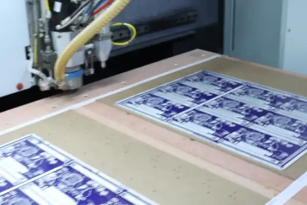
WHEN COPPER, NOT THE MOSFET, IS THE HOTTEST COMPONENT ON THE BOARD
I’ve been doing power electronics design for a few years now, and a recent MPPT controller PCB gave me a real headache — worth sharing. Most people obsess over the algorithm when it comes to MPPT — perturb-and-observe, incremental conductance, endless code refinement. But what actually keeps a board running stable was never the software. It was the copper. Yes, the copper layer on the PCB itself.
A while back I designed a Buck-topology solar charging board with an input voltage peaking at 150V, feeding a 48V battery bank at roughly twenty-some amps. Initially I assumed the standard 2 oz copper with slightly wider traces and extra vias would be enough. At full-power testing, the board’s temperature rise was absurd — you couldn’t rest a finger on the power loop area for more than a second. A thermal scan revealed the hottest spot wasn’t the MOSFET or the inductor — it was the copper traces I’d assumed were plenty wide. They were behaving like heating elements, quietly dissipating power across every square inch. After digging into I²R losses, I realized that under high current, thin copper can’t be compensated for by cross-sectional area alone — current density concentrates near the surface, and only thicker copper actually brings resistance down. So I switched vendors, found a dedicated heavy copper PCB shop, and pushed copper thickness to 4 oz. The effect was immediate — same trace width, temperature rise dropped by almost half. That’s when I understood: in an application like an MPPT Controller PCB, with high current and heavy thermal stress, what you’re really choosing isn’t the trace — it’s the thermal pathway. Don’t skimp on board material cost; find a reliable heavy copper PCB manufacturer and every parameter on the board improves noticeably.
The inductor was another component that made me cry. On one revision, I sized it based on current at the maximum power point, keeping the ripple ratio conservative at around 0.3, thinking that would balance core and copper losses nicely. It ran fine for the first few months — but after summer, customers reported the equipment tended to reboot in the early morning and evening. When I brought a unit back for testing, I found the inductor was intermittently saturating during low-light conditions when MPPT was rapidly adjusting the duty cycle. At the edge of cloud cover, solar output power jumps instantaneously, and the input current peak spiked well above my steady-state calculation — enough to slam the inductor straight into saturation, with the resulting current spike tripping the chip’s protection circuitry. I upgraded the inductor, not just by rated current but by choosing a part with a saturation current at least 1.5 times the peak current, and switched the core material from ferrite to iron-silicon-aluminum, which finally solved it for good. Inductor margin really can’t be calculated from steady-state conditions — you have to size it for the worst-case transient.
On topology, a lot of newcomers agonize over Buck versus Boost, or think a Buck-Boost solves everything once and for all. My view is: if a single stage can solve it, don’t overcomplicate it. I once built a Boost design — a low-voltage panel charging a high-voltage battery — where the control logic was relatively simple and the duty cycle range was narrow. But Boost’s startup inrush is a bit tricky to handle: the output capacitor has to withstand the high voltage, and if the switching transistor ever stops working, input connects straight through to output — a risk that must be clamped in the circuit. Buck, on the other hand, steps down naturally but demands a lot from the high-side driver — the bootstrap capacitor issue I mentioned earlier has tripped up plenty of experienced engineers. Many integrated control chips handle these issues now, but in layout, minimizing the power loop area is always priority one. In a Buck circuit, the loop formed by the input capacitor, high-side switch, low-side switch, and ground — if the inductor sits even slightly away from that switching node, you’ll see absurd ringing. When laying out an MPPT Controller PCB, I make a habit of placing the two MOSFETs and the input capacitor as close together as physically possible, soldering one end of the inductor directly onto the switching-node copper, keeping that copper island as small as possible, and using a solid ground plane on the back of the whole loop as a shield. The resulting waveforms are clean, and efficiency goes up.
Over the past couple of years I’ve also started using aluminum or copper-based substrates from heavy copper PCB suppliers for heat dissipation, especially for fanless outdoor controllers, where high power density makes heat unavoidable. Heavy copper doesn’t just carry high current — it also spreads heat quickly from component leads across the whole board, then out through the enclosure, which is far cleaner than bolting on extra heatsinks.
A friend in solar recently vented to me that a batch of his MPPT controllers had burned out several units during burn-in testing. When we opened them up, the copper around the inductor was discolored from heat. He assumed the inductor’s saturation current rating was insufficient and swapped in a bigger part — same problem. I had him send the PCB over, and under magnification the root cause wasn’t in the components at all — his PCB supplier simply couldn’t produce genuine heavy copper.
That batch of boards was rated 4 oz copper, but a cross-section revealed the corners were barely half that thickness, with obvious over-etching on the high-current paths. A board like that can limp along at 20-30A, but the moment current spikes to 50-60A, the copper becomes a heating filament, and even the best inductor won’t save it. I introduced him to a dedicated heavy copper PCB shop, they redid the batch, and the problem disappeared immediately. That shop’s habit was giving generous inner-layer copper thickness and spreading high-current loops across wider copper with more vias, instead of just quoting you a copper-thickness number and calling it done.
So now, when I choose a heavy copper PCB supplier, I don’t just look at the copper thickness they claim — I need to see whether they’ve actually done power-board work before. Plenty of heavy copper PCB manufacturers simply force a conventional process to hit a copper-thickness spec, while missing details like the heat-spreading copper design around pads or solder mask opening sizes — small oversights that introduce mysterious noise during high-current sampling.
CURRENT SAMPLING: THE EASIEST PLACE TO GET IT WRONG
Speaking of current sampling, this is one of the easiest places to mess up on an MPPT controller PCB. Many people assume that a high-precision sampling resistor guarantees accurate readings — then power up the board, look at the oscilloscope, and see a waveform full of scary glitches. The problem is in the layout: if the sense lines at either end of the sampling resistor aren’t routed as tightly coupled differential pairs, or get exposed to the magnetic field from high-current copper, the returned signal is full of noise. I make a habit of hollowing out a ground layer directly beneath the sampling resistor, routing the differential lines above and below it, keeping the sense lines tightly together, and staying far away from strong interference sources like the inductor and MOSFET. This way, even a 0.5 milliohm resistor produces a clean signal, and MPPT tracking doesn’t jump around erratically.
Another commonly overlooked issue is the PCB’s own temperature drift. Especially on high-power MPPT controllers used outdoors, where the board sees sub-zero winters and scorching summers, copper resistivity shifts noticeably. If the sampling section lacks temperature compensation, or uses a sampling resistor with poor temperature drift performance, current readings will drift. I had a prototype that measured 0.5% current accuracy at room temperature at the factory, but after two hours on a rooftop in the sun, the reading was off by nearly 3%. After switching to a batch of 50ppm metal-foil resistors and recalibrating, I finally got full-temperature-range accuracy stable within 1%. Every detail on an MPPT Controller PCB has to be validated against real-world conditions — lab data alone isn’t enough.
THE SAMPLING CIRCUIT MATTERS MORE THAN THE TRACKING ALGORITHM
In this line of work, the biggest pitfall I’ve hit isn’t the algorithm — it’s the board itself. A lot of people pour all their effort into MPPT tracking speed and neglect the unassuming resistors and thin copper in the sampling loop. Then temperature rise gets out of hand and the readings drift wildly off.
On one project I handled, input-side voltage regularly climbed to 130-140V, with peak current around 40A. Early on, to save time, I laid it out on a standard four-layer double-sided board. During testing, the board got too hot to touch, sampling values jumped around, and the MPPT controller simply shut down. I eventually found a dedicated heavy copper PCB supplier whose heavy copper PCB manufacturer could produce 4 oz, even 6 oz copper. After a fresh prototype run, the internal resistance of the high-current loop dropped by at least half, and the heat problem quickly came under control. That experience made me realize that power traces on an MPPT Controller PCB aren’t just “connected” — copper thickness itself is an underrated passive component.
I’ve lost even more time to sampling issues. Early on I chose a thick-film alloy resistor rated at 50ppm temperature drift for current sampling, assuming software compensation would handle the rest. In practice, the internal temperature gradient of the board was far from linear — the resistor body and the NTC thermistor differed by several degrees, and the compensation algorithm was never properly aligned. Eventually I abandoned thermistor-based compensation entirely and switched to a manganin sampling resistor, whose temperature coefficient is nearly flat between 20°C and 100°C, paired with a four-terminal Kelvin connection that fully separates the sampling point from the power trace. That change eliminated a huge amount of calibration overhead, and gave me a whole new appreciation for what a “resistor” actually is — it’s not just a resistance value, it also has thermal EMF, parasitic inductance, and even resistance drift from mechanical stress, any of which can ruin a carefully tuned voltage sampling circuit.
Voltage sampling has even more fine details. Many designs simply connect a resistor divider network straight to the ADC, assuming that as long as the divider ratio is correct, it’s fine. But in high-voltage scenarios, the voltage gradient across the divider resistors can attract ions from the air, and long-term operation in humid environments can form faint conductive paths on the PCB surface, directly shifting the divider ratio. I now insist that all high-voltage divider resistors be mounted with elevated clearance, that both sides of the board get moisture-proof coating, and I even require the heavy copper PCB supplier to leave the divider network area free of copper pour, to increase creepage distance. Requirements like these are ignored by ordinary quick-turn board houses — only a heavy copper PCB manufacturer willing to cooperate will actually go through them item by item during engineering review.
There’s another point rarely mentioned: the routing between the sampling resistor and the ADC. If the PCB uses heavy copper, the magnetic field generated by the high-current loop can couple into small-signal traces, inducing tens of microvolts of fluctuation on the sampling lines — a disaster for an MPPT controller that needs accuracy above 99%. My current approach is to always keep voltage-sampling traces off the high-current layer, cramming them into a signal layer instead, and placing a differential RC filter right at the sampling resistor’s terminals, using NP0 capacitors and 25ppm metal-film resistors to push the noise entering the ADC as low as possible. This circuit looks simple, but on a real MPPT Controller PCB, even a slightly imperfect layout produces a waveform full of glitches that no amount of software filtering can rescue.
At the end of the day, an MPPT controller isn’t purely an algorithm problem — it’s a board that blends analog circuitry with high-power digital circuitry. Whether it can survive continuous full-power operation under direct sunlight, and whether its readings stay accurate, depends entirely on how you treated the sampling resistors, how you chose your copper thickness, and how well you communicated your real requirements to the heavy copper PCB manufacturer. None of this is written in books — you only really learn it after you’ve burned a few boards and lost some data.
TWENTY BOARD REVISIONS, AND THE LESSON WAS ALWAYS THE SAME
I’ve been building solar charge controllers for close to a decade, and across more than twenty revisions of MPPT Controller PCBs, most of the pitfalls I hit had nothing to do with the algorithm — they were all hardware. Plenty of articles online obsess over perturb-and-observe or incremental conductance, as if perfecting the algorithm alone can push power output higher. That’s simply not how it works. If your board layout is weak and the copper foil is as thin as paper, even the smartest MPPT algorithm is useless.
On my first high-power prototype, I made a particularly dumb mistake. To save cost, I chose an ordinary PCB shop with only 1 oz copper. Running 40A, the power traces got hot enough to fry an egg. MPPT kept working, but as the sampling resistor’s temperature drift climbed under heat, the entire power tracking point shifted, and efficiency dropped to an unacceptable level. I then searched everywhere for a real heavy copper PCB manufacturer, going through three or four before finding one that was actually reliable. Genuine heavy-copper specialists operate at a completely different level in etching and lamination control compared to ordinary shops — 4 oz copper carrying high current keeps temperature rise firmly in check, and sampling accuracy stays stable. So now I’m extremely picky about heavy copper PCB suppliers — not just whether they can technically do it, but whether they can guarantee copper thickness uniformity and plating consistency, because those details directly affect the long-term reliability of your MPPT board.
Something else many people don’t realize: the core of MPPT hardware design really comes down to the power loop. The tighter you can make the high-frequency loop area formed by the DC-DC section’s input capacitor, inductor, MOSFET, and output capacitor, the lower the switching noise coupling into the current-sampling circuit. I once revised an old design just by re-planning the four-layer stack-up, strictly single-point-connecting power ground and signal ground, and MPPT’s tracking jitter at low power dropped by nearly half. That single change delivered more benefit than hours spent fine-tuning PID parameters in code.
As for multi-peak tracking, I’ve largely given up on solving it through pure hardware scanning. Some designs rely on a hardware scanning circuit to quickly plot the IV curve — a reasonable idea in theory, but in practice, forcing the MOSFET into linear-region operation for a very short window to sweep voltage brings a pile of thermal and drive-protection headaches. I eventually switched to a periodic brief short-circuit method combined with software-based global scanning — hardware’s only job is to keep the sampling path fast and low-noise, capturing a clean current and voltage waveform within those tens of milliseconds, and leaving the rest to the processor. It turned out to be more reliable and far less demanding on the hardware. In the end, MPPT success isn’t about who has the fanciest algorithm — it’s about who can pin down noise and heat on the hardware side well enough to deliver power steadily.
A 3KW SYSTEM THAT TAUGHT ME TO TAKE COPPER SELECTION SERIOUSLY
In solar controller design, I’ve hit more pitfalls in the PCB than anywhere else on the road. High-power MPPT controllers in particular simply cannot be handled with an ordinary multilayer board. The first time I built a 48V system rated at 3kW, with input voltage running above 120V year-round and peak current close to 30A, the copper foil started smoking the moment we powered up the first prototype — I can still remember that burnt smell. Investigating further, I found the board house’s default 1 oz copper was like a strand of hair standing against a flood under that continuous high current. Since then, I’ve never been careless about screening heavy copper PCB manufacturers again.
An MPPT Controller PCB is a completely different animal from an ordinary digital board. It has to simultaneously handle high voltage, high power, fast switching noise, and harsh outdoor conditions. On the input side, solar array voltage alone can reach tens or even over a hundred volts, and the current isn’t small either — an ordinary PCB’s trace drop and heat generation simply can’t be contained. My rule now is: above 500W, go straight to 3 oz copper or thicker, and only work with a heavy copper PCB supplier that can genuinely deliver it — not one that claims to but only plates a thin, deceptive layer of copper on the inner and outer layers. I once tried a supplier claiming 4 oz, only to find under cross-section that the actual thickness was under 2.5 oz — the board kept tripping thermal protection during operation, and control logic fell apart every time the load dropped.
Finding a heavy copper PCB manufacturer is a genuinely technical exercise — you can’t just take their brochure’s word for it. I usually ask whether they can achieve 6 oz copper, what trace width and spacing they can control to, and ask for thermal-stress test data. In a high-power MPPT power loop — especially the section from input capacitor to inductor to switching transistor — peak current stacks on top of ripple current, so copper current-carrying capacity can’t be calculated as a simple average; you need real margin. My rule of thumb is at least 0.5mm of trace width per amp (for 4 oz copper), with traces kept short and thick, not routed in a lazy serpentine pattern. Input capacitor placement is also heavily dependent on copper thickness — since bulk electrolytics and MLCCs are typically mixed, if the copper is too thin, ESR- and ESL-driven ringing will make the whole board hum, seriously degrading power tracking accuracy.
On the voltage side, a wider input voltage range demands greater PCB insulation clearance. For a 150V system, air gap and creepage distance need to follow IEC standards, and heavy copper etching brings pronounced sidewall undercut — if you’re not careful, burrs on the trace edges can trigger arcing under high voltage. On one project, poor process control at the heavy copper PCB supplier caused insulation resistance between traces to fall short of spec — humid weather caused direct leakage, and the MPPT controller kept misreading input voltage, jumping erratically while sweeping the power curve. Switching to a heavy copper PCB manufacturer with ENEPIG plating, and adding double slotting on the input side, finally resolved it completely.
At the end of the day, when building an MPPT controller, don’t fixate only on software algorithms and component selection — the PCB is the real physical foundation. Especially for high-power, high-voltage input scenarios, finding a reliable heavy copper PCB supplier does more for you than months of PID tuning. On every new project now, the first thing I do is pull the power-loop requirements out separately and sit down face-to-face with the board house’s engineers — copper thickness, trace width, insulation, heat-dissipation copper thickness — nailing down every item, and insisting they provide cross-section reports. Fewer detours all come down to these fundamental details.
TREATING THE PCB AS A THERMAL SYSTEM, NOT JUST AN INTERCONNECT
Over years of electronics design, the biggest pitfall I’ve hit is underestimating the physical limits of the PCB itself. Many people pour all their effort into MPPT’s algorithm and control logic, believing that if the code is elegant, the controller will run smoothly — that’s simply not how it works. I had a batch of early-generation MPPT controllers whose firmware went through several revisions, yet the field return rate stayed stubbornly high. When we finally cross-sectioned the failed boards, the problem turned out to be in the least glamorous place — insufficient copper thickness and a fundamentally flawed routing approach.
Back then I was using ordinary 1 oz copper PCBs, relying on wider traces in the power loop to compensate for current-carrying capacity. On paper, the calculated values all checked out, but come summer, inside a sealed metal enclosure outdoors, once board temperature climbed, the copper’s current-carrying capacity dropped sharply. Worse, repeated thermal stress gradually produced micro-cracks in the copper near the vias, eventually burning out the entire power stage. When we opened the failed boards, the burn point wasn’t the MOSFET at all — it was the copper foil in the high-current loop that had melted through. That’s when it fully sank in: for an MPPT controller, the PCB isn’t just an interconnect tool — it’s part of the power loop itself. Its copper thickness, stack-up, and thermal path directly determine the product’s lifespan.
Afterward I went looking for a genuinely reliable heavy copper PCB manufacturer, and the process was harder than expected. Plenty of vendors claim they can do heavy copper, but their actual process capability tops out around 3-4 oz, with poor sidewall etch control and trace-width precision that falls short — not to mention copper-thickness uniformity. Suppliers truly capable of 6 oz, even 10 oz, are rare domestically, and their understanding of lamination, drilling, and solder mask is on a completely different level. For example, during lamination of heavy copper boards, resin flow and fill capability become a major hurdle — get it wrong, and you end up with plenty of interlayer voids, which directly break the internal thermal pathway. On my first batch of heavy-copper prototypes, thermal imaging showed a distribution wildly different from simulation. Cross-sectioning revealed a clear resin-starved zone between the inner-layer copper and the prepreg — heat was trapped locally, and thermal efficiency suffered badly.
It took three to four months working with that heavy copper PCB supplier, revising the stack-up and lamination parameters multiple times, before we finally brought thermal resistance down. The resulting boards, tested at full load in a 70°C ambient environment, showed nearly 40% lower temperature rise than the previous ordinary boards, with much more even temperature distribution across the power region. That difference is critical for an MPPT controller, because the power inductor, MOSFET switching losses, and freewheeling diode heat all concentrate in the same area of the PCB — insufficient copper thickness or a poor thermal path creates a hotspot, and once a hotspot forms, the MOSFET’s Rds(on) spikes, losses climb further, and it becomes a vicious cycle where burnout is just minutes away.
My understanding of MPPT controller PCBs has fundamentally changed as a result. It’s not about finding a heavy copper PCB manufacturer and calling it done — you need to design the PCB as a thermal system from the very start. Copper thickness is just the baseline; what matters more is making the copper form a genuine low-thermal-resistance channel not just laterally, but vertically too — for instance, using large-area copper-filled vias, or designing in embedded copper blocks so heat can travel directly from the surface-mounted power components down to an aluminum heat-sink substrate or the enclosure. Ordinary PCB shops never think about these details for you — only heavy copper PCB suppliers genuinely experienced in this space can point out how to optimize the stack-up and thermal structure. I’d go so far as to say that the quality of an MPPT controller is already 70% decided the moment you choose your PCB supplier.
RIPPLE, TEMPERATURE DRIFT, AND THE THINGS NO TEXTBOOK MENTIONS
Over years of building solar controllers, the deepest pitfall I’ve hit was never the algorithm, and never the topology — it was the circuit board itself. Most people pour their effort into MPPT tracking speed and accuracy, while overlooking the substrate carrying it all — the MPPT Controller PCB — which is the most consistently underrated part of the whole system. Once power scales up, you quickly discover just how hard it is to find a reliable heavy copper PCB manufacturer.
On one project, an off-grid energy storage MPPT design, input current was rated at 40A with peaks up to 55A. Following conventional practice, I used 2 oz copper with generously sized trace width. The prototype ran at full solar power for under twenty minutes before the board got too hot to touch, and the copper foil delaminated from the substrate. Cross-sectioning revealed that the expansion coefficient mismatch caused by the temperature rise had literally torn the vias apart. I went through nearly every heavy copper PCB supplier in the Pearl River Delta region — most shook their heads the moment we mentioned needing 4 oz or 6 oz copper with impedance control. Eventually I found a factory specializing in power boards and automotive electronics, using a multi-lamination heavy-copper process that brought conduction resistance and thermal stress down. Since then, every power-stage MPPT board I design puts all high-current loops on heavy copper, with power ground and signal ground completely separated in layout and merged at a single point — that’s what finally controlled the ripple and heat caused by PCB internal resistance.
Speaking of ripple, it’s a sneaky problem. You’d assume it’s just noise on the output, but it actually feeds back and interferes with MPPT sampling. The controller relies on voltage and current sampling to determine the maximum power point — if the sampled signal carries hundreds of millivolts of ripple riding on top, even the most precise algorithm is useless. I saw one design where poor input capacitor placement let inductor ripple current couple directly into the current-sampling resistor terminals, causing the controller to repeatedly misjudge during changing light conditions and dragging overall efficiency down significantly. After redesigning the board with tightly-routed differential sampling lines and a low-ESR hybrid capacitor combination on the input side, we brought ripple down below 30mV. That’s when it becomes clear: MPPT hardware design is fundamentally a fight for precision against noise and parasitics.
On the controller side, I’ve increasingly come to prioritize temperature drift and long-term stability. Some MPPT chips perform beautifully in the lab, but after a summer of outdoor sun exposure, their reference voltage drifts. So I now reserve board space for an external reference source — a few extra dollars in cost, but sampling accuracy stays solid for three to five years. I also add a firmware-level protection layer — continuously monitoring battery voltage and forcibly limiting the duty cycle once it drops below a threshold, preventing inductor saturation. That strategy has saved me more than once, because some lithium batteries see a sudden jump in internal resistance during deep discharge, and if the controller keeps outputting at full duty cycle regardless, current can spiral out of control instantly.
In the end, a lot of people building MPPT controllers fixate on conversion efficiency numbers early on, but what actually determines whether a product survives three to five years in the field usually comes down to invisible details: is the copper thick enough, how is the ripple path routed, where is the sampling reference point, and does the protection mechanism respond in hardware first or wait for software to slowly figure it out. None of this is written clearly in any textbook — you can only build that knowledge through repeated failure and teardown. If I could start over, I’d put PCB reliability and power integrity first, and let the algorithm follow naturally.
WHAT REALLY BURNED A CUSTOMER’S CONTROLLER
A friend running an off-grid power station recently vented to me — another batch of his MPPT controllers had burned out. I opened one up and had to laugh: the copper foil in the power loop was as thin as paper, and it had simply carbonized under high current. He’d gone with an ordinary PCB shop to save time, saving thirty yuan per board — and the labor and time spent on repairs afterward could have bought two batches of good boards instead.
Anyone in solar knows the deal: sunlight looks free, but capturing it reliably is full of hidden traps. MPPT itself is a precision game — a fraction of a percent off in sampling accuracy can mean missing the optimal power point — but many people overlook that the substrate carrying all that precision circuitry is the real weak link. After seven or eight years in this field, my deepest takeaway is: never cut corners on heavy copper PCBs.
Heavy copper PCB suppliers on the market today generally fall into two camps: those who genuinely understand power-electronics thermal design, and those who simply force a standard process to hit a thicker copper spec. The difference? The latter’s boards may claim 4 oz inner-layer copper, but current distribution ends up uneven, with local hotspots dragging conversion efficiency down by several percentage points. Last year I tested sample boards from three different vendors, and the temperature rise under the MOSFET traces varied by nearly 20°C between them — same circuit design, same component placement — purely down to differences in board manufacturing process, which decides whether the product survives midday summer sun.
When selecting a heavy copper PCB manufacturer, I don’t care how many years of experience their website claims — I go straight to two questions: can you do multilayer mixed lamination above 6 oz copper thickness, and can via-wall copper uniformity after lamination be controlled within ±10%? A vendor willing to answer directly and show you a cross-section report is usually solid.
Another commonly overlooked point is the glass transition temperature (Tg) of the base material. Many outdoor solar controllers still use ordinary FR4 to save cost — with a Tg around only 130°C. Once the internal enclosure temperature climbs under sun exposure, the substrate begins to soften, its expansion coefficient shifts abruptly, and micro-cracks slowly develop under BGA solder joints or large chip footprints — a failure mode that’s essentially undetectable at first, only surfacing three or four months into field operation as inexplicable power loss or communication dropouts.
I also want to say a few unpopular words about MPPT design logic itself. The whole industry is currently piling wireless modules — LoRa, WiFi, cloud platforms for component-level monitoring — into controllers. It’s flashy, but plenty of manufacturers are shipping products in volume without even nailing basic Buck inductor selection. I’ve torn open plenty of so-called smart solar optimizers where the internal routing looks like a spider web — power ground and signal ground unstratified and scattered — with common-mode noise high enough to crash the MCU.
The right approach is to nail the analog front end first — get the current and voltage sampling signal-to-noise ratio high enough that the algorithm can track the maximum power point reliably under fast-changing overcast light — and only then add communication features as a bonus, not the other way around.
Domestic heavy copper PCB supply chains have actually progressed quickly over the past couple of years. Finding a manufacturer capable of 8 oz+ heavy copper used to mean queuing up with the handful of established South China plants, with lead times of three to four weeks and steep pricing. Now, mid-sized manufacturers focused specifically on power-electronics substrates have emerged across the Yangtze and Pearl River Delta regions, with process quality matching the big shops and much better collaboration — willing to repeatedly adjust impedance and stack-up plans with you, which matters enormously during the development phase.
A tire pressure sensor that lost signal after six months, taken apart,
A fiber laser marking machine that ran perfectly for six months can
A Microgrid Controller PCB kept showing signal jitter during grid-tied testing, and
- Expert en production de petites et moyennes séries
- Fabrication de circuits imprimés de haute précision et assemblage automatisé
- Partenaire fiable pour les projets électroniques OEM/ODM
Heures d'ouverture : (Lun-Sam) De 9:00 à 18:30
Get quote, solution or any question, Andre always here to help