

What Documents Are Required for PCB Production: A Field Guide From Real Industrial Weighing Controller PCB Projects
Many engineers focus too much on technical parameters early on and overlook
A 10-Layer Robot Controller Board Delayed Two Months by a Prepreg Specification Error
Not long ago we had a six-axis welding robot project where the controller revision stalled on the PCB for a full two months — the problem was not in the schematic, nor in the layout, but in the multilayer board’s material selection and lamination process. That board was a 10-layer Industrial Robot Controller PCB, running TI’s DSP and a multi-axis servo interface — the moment the sample came back and was powered up, interlayer capacitance deviation was absurdly high, and the differential signal eye diagram was completely closed. Investigation eventually revealed that a certain multilayer PCB supplier had used out-of-spec prepreg and had even reversed the lamination order. This incident made me completely abandon any illusion that “close enough is fine.”
Building a robot controller board, in many cases, is far more than getting the circuit to function correctly. The moment a joint motor moves, vibration and thermal cycling on the board amplify any process flaw. I have seen far too many people treat a robot controller PCB like a generic industrial control board — a 4-layer board, standard-Tg laminate, loose impedance control — and end up with even the servo valve’s real-time commands dropping packets. We later made it mandatory that any core board involved in motion control must go through a multilayer PCB manufacturer’s rigid lamination process, starting at 8 layers minimum, with inner-layer copper thickness no less than 2oz, and thermal-stress simulation always required. Do not think this is over-engineering — half a year ago, an AGV board that skipped blind/buried vias saw its encoder feedback jump several revolutions under geomagnetic interference — a loss far beyond the cost of a few boards.
When choosing a multilayer PCB supplier, many people look at unit price first — which is exactly the biggest trap. The fatal weakness of an industrial robot PCB is often not the design — it is batch-to-batch consistency. I worked with several suppliers, including one of decent scale, whose dielectric constant drifted with every batch that came back, forcing us to re-tune PI parameters every single time. I eventually only worked with original manufacturers who could provide laminate traceability and impedance test reports — even accepting a longer lead time — refusing to gamble the entire robot’s reliability on anything less. The multilayer PCB manufacturer we currently use works with Panasonic Megtron 6 material, combined with resin via-plugging and a double-lamination process — the resulting boards show excellent consistency, and once plugged into a servo drive, the current loop’s response curve nearly overlaps with simulation.
Many people think a robot PCB is just a matter of stacking components, but my experience over the years is that it behaves more like a precision structural component. An asymmetric stack-up warps; uneven distribution of thermal copper causes localized overheating; a single tiny via crack can send the entire robot suddenly out of control. In building robot controllers, what it ultimately comes down to is understanding the board’s physical characteristics, and finding a multilayer PCB manufacturer who genuinely knows this domain. Do not treat the board shop as merely a fabrication vendor — treat them as an engineering partner. Lay out your demanding process requirements, and see whether they can absorb them and push back with their own optimization suggestions — that is the kind of partner worth a long-term relationship.
Communication Determinism Over Raw Compute: Lessons From Six-Axis, SCARA, Cobot and AGV Projects
I have been in robot-controller hardware for six or seven years now. Many people assume this is just a matter of stacking a high-performance board, running Linux or an RTOS, and hanging a motor driver off it. In actual practice, it is nothing like that. The Industrial Robot Controller PCB in your hands is fundamentally a signal hub that has to run stably over the long term in an extreme physical environment — it is not a simple logic-connection diagram.
My earliest trap was on a six-axis welding-robot project. At the time, the embedded team pushed compute power as high as possible — DSP plus FPGA, floating-point capability maxed out — assuming trajectory planning would be flawless. On site, the robot’s end effector shook like a sieve during high-speed arc welding. Two months of investigation eventually traced it to the communication bus. The multilayer PCB manufacturer we used had experience mostly in consumer electronics, and the stack-up structure never accounted for length-matching and impedance consistency on high-speed differential pairs, causing EtherCAT frames to start dropping right at the physical layer. Do not dismiss it as just a few tiny dropped frames — in multi-axis coordinated motion, once each joint’s synchronization clock goes chaotic, the trajectory falls apart entirely. That lesson taught me: in robot-controller hardware, communication determinism absolutely outranks raw compute power alone.
Later, working on a SCARA sorting robot, we ran into a completely different challenge. This kind of robotic arm has an absurdly demanding cycle-time requirement — grabbing and placing over 120 times per minute means the control cycle has to compress down to a few hundred microseconds. This requires signal loops on the board to be extremely short — unlike a six-axis robot, which allows long cable runs. We found a multilayer board supplier at the time who recommended a 2nd-order HDI with buried vias, pressing the driver interface and encoder feedback loop directly underneath the main chip. That board had 10 layers total, with 3 routing layers dedicated specifically to signal return paths — cost went up considerably, but millisecond-level jitter was genuinely suppressed in the end. This case taught me that choosing a multilayer board process for a specific robot form factor is not about checking boxes on a parameter sheet — you have to understand the robot’s physical motion rhythm, then work backward to the electronic flow rhythm required on the circuit board.
Collaborative robots follow yet another logic entirely. Safety redundancy is not achieved through software patches — it is carved into the hardware. When we built our first prototype to pass ISO 13849 PLd certification, it was rejected outright by the certifying body because the safe-torque-off loop lacked physical isolation. In the re-spun main control board, we specifically split two independent power domains, used dual-channel redundant logic, and even routed the safety MCU’s crystal oscillator independently. That board also used a supplier specializing in industrial multilayer boards, who applied special treatment to creepage distance in the high-voltage isolation region during lamination, achieving a withstand-voltage rating one grade higher than standard FR-4. I found that designing a cobot controller PCB is actually more like planning two brains on one board that do not interfere with each other yet mutually supervise each other — far more complex than simply increasing compute power.
AGVs present yet another situation. Their controller hardware has to withstand vibration and dust, while also accounting for the instability of onboard battery power. One controller revision, to minimize size, used an 8-layer board, integrating navigation, obstacle avoidance and wireless communication all together. At volume production, we found that switching noise from the on-board DC-DC module coupled through the ground layer into the IMU’s analog signal lines, causing gyroscope zero-bias drift. We later adjusted the stack-up, splitting analog ground from digital ground, bridging them at a single point with a ferrite bead — signal finally cleaned up. This process made me realize that if a multilayer board supplier simply fabricates to the drawing without understanding the intended signal flow on the board, what they produce is worthless. You need to find a team willing to sit down and discuss stack-up strategy, impedance control, even thermal-simulation results with you — not one that just receives a Gerber file and waits for you to collect the boards.
Now, when choosing a multilayer PCB manufacturer, I do not pay much attention to their advertised HDI order or minimum trace width and spacing — those are basic capabilities. What I care about more is whether they have actually built genuine industrial motion-control boards, and whether they understand how to handle ground bounce and EMI in an environment of sustained high-frequency interrupts from multi-axis servos. Robot-controller hardware is fundamentally a system extremely compressed in both the time and physical dimensions — it does not get as many trial-and-error opportunities as consumer electronics. The cycle from board design, through SMT assembly, to full-system testing is long, and if signal-integrity problems arise from board-shop process limitations, troubleshooting can drive you to the brink.
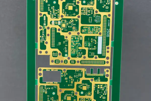
An EtherCAT Eye-Diagram Failure That Forced a Complete Stack-Up Redesign
A few years ago, building a six-axis robot controller, we nearly had the entire project dragged down by an unassuming PCB problem. At the time, everyone on the team was focused on main-chip selection — whether compute power was sufficient, whether it could run a real-time system, whether the Ethernet port supported industrial protocols — argued back and forth endlessly. Then the prototype came back assembled, and the moment we ran the EtherCAT bus with all six axes coordinated, an oscilloscope hooked onto the Ethernet differential lines showed an eye diagram that could barely open at all — frames dropped constantly, and the servo alarmed. Honestly, that feeling was extremely frustrating — you assume the core difficulty is in algorithms and software, only to be choked by a handful of traces.
We later sent this Industrial Robot Controller PCB’s original design files to a multilayer PCB manufacturer specializing in industrial control boards, and their engineer said immediately, upon looking at it, that our four-layer stack-up was simply wrong — a thick core board separated the signal layer from the reference layer, and impedance was completely out of control. Furthermore, our gigabit Ethernet differential pair crossed a power-plane split underneath it — the entire return path was a fragmented mess. Hearing this explanation, we realized that the Ethernet-routing habits typically used for switches and computer motherboards simply do not transfer to a robot controller, because here you not only have high-speed digital signals — you also have high-current motor-driver ripple and analog conditioning for encoder feedback, all crammed onto one board together.
We later re-fabricated the board with a different multilayer PCB supplier who understood mixed high-speed-signal and power design. Following their recommendation, we switched to six layers, routed critical signals on inner layers, wrapped both sides with complete ground planes, strictly controlled the Ethernet differential pair to 100Ω impedance, and never let it cross a split along the way. Testing the new board, the eye diagram was as clean as a textbook illustration — packet loss disappeared entirely, and the controller ran a thousand cycles rock solid. This experience left me fully convinced of one thing: no matter how expensive the chip, no matter how advanced the industrial Ethernet protocol, if this PCB layer is not solidly built, the entire robot controller has a high probability of becoming a useless brick.
Now, when discussing robot-controller development with people, I rarely talk about clock speed or which vendor’s core board — I ask more often: who built your PCB, have they seen the waveform of servo current backflowing into digital ground under a 20kg load, and do they understand time-delay drift of Ethernet signals across -40°C to 85°C. Plenty of suppliers who do multilayer board prototyping have adequate capacity, but genuinely turning an industrial robot controller PCB from a schematic into a finished product that holds up on the production line without misbehaving requires a manufacturer with engineering intuition — one who obsesses over stack-up, over return paths, over hot-cold cycling reliability. Without finding such a partner, even the best-designed controller remains a lab showpiece.
AM5728 RGMII Signal Integrity, Thermal Vias and Dual-PHY Isolation
Over these years building industrial robot controllers, the biggest headache has never been software algorithms — it is that unassuming baseboard. Every project kickoff, I spend more time on the Industrial Robot Controller PCB than on writing motion-control code. Many people think it is just drawing a board and finding a multilayer shop for prototyping — but once you actually deploy a high-performance processor like the AM5728, you realize it is nothing that simple.
The prototype in my hands originally used a cheap multilayer board supplier to save schedule time, and the moment the board came back and was powered up, strange things happened. Ethernet would intermittently drop — not a total outage, just a few dropped packets every few minutes — and an oscilloscope capturing the RGMII eye diagram showed it barely opening at all. Investigation revealed that shop’s lamination process simply could not control dielectric thickness on a 6-layer board — impedance deviation ran beyond 15%, ruining signal quality between the PHY and the AM5728 entirely. Since then, I have never dared underestimate multilayer PCB manufacturer selection again. It is not enough for the board to merely function — at gigabit RGMII speeds, stack-up design, copper-foil roughness and glass-weave effects can each plant a landmine in your Ethernet communication.
Thermal management taught me an even harder lesson. The AM5728’s power consumption looks modest, but cram it together with two DDR3 chips, an Ethernet PHY and a pile of power modules inside a sealed control cabinet, and heat accumulates fast. I tried running it bare, without a heatsink — at 25°C room temperature, core temperature spiked past 85°C within half an hour. I eventually planned the thermal path directly into the PCB design stage — filling the area under the AM5728’s thermal pad with thermal vias straight through to the bottom-layer copper, then attaching an aluminum substrate for heat dissipation. This is not purely a hardware matter — it is also tied to the multilayer PCB supplier’s process; some shops’ via-plugging resin has terrible thermal conductivity, and filling vias with it actually turns them into a thermal-insulation layer instead. Now I only work with multilayer PCB suppliers who can provide copper-paste via filling or thermally conductive adhesive fill — otherwise heat has nowhere to go, the CPU throttles, and robot trajectory precision collapses immediately.
For industrial Ethernet, I never use a shared PHY and transformer. On a robot controller, I make a habit of thoroughly separating the debug network port from the EtherCAT ET port — physically using two independent PHY chips, even placed in different regions of the board. Some think this is wasteful, but on an early prototype, I saw an oscilloscope probe touch the debug network port and the EtherCAT slave immediately dropped offline — interference coupling was severe. The AM5728 itself integrates two Ethernet MACs, and you might as well use both, but the return paths absolutely must be separated in layout — digital ground cannot be casually split, and current paths need to be kept firmly in mind. I generally require the multilayer board shop to compress the spacing between adjacent power and ground planes to form good plate capacitance — this helps suppress high-frequency noise far more effectively than adding any number of ferrite beads downstream.
Looking back now, building this kind of robot-controller board is often not a chip-selection problem — it is whether you can find a trustworthy multilayer board manufacturer willing to grind through stack-up decisions with you, willing to run impedance-coupon testing to your specifications, rather than conveniently handing you a standard template. I got burned by this and gradually built my own supplier list — every project now involves repeated upfront confirmation of key parameters with the factory’s engineering department, such as dielectric-thickness tolerance, copper-thickness uniformity, and the solder-mask ink’s dielectric constant. All these details eventually feed back into whether the AM5728 can run stably at full performance, and whether the Ethernet PHY can hold up under harsh conditions. In hardware work, at the end of the day, you are wrestling with these invisible physical quantities — treat them casually, and they will slap you hard at the customer site.
From Double-Sided to Multilayer: Fixing EtherCAT Synchronization Jitter
I remember, a few years back, revising the control board for a six-axis robotic arm, when I had no real concept of multilayer boards yet — I casually found a double-sided-board shop for prototyping, and EMC was a total mess: the moment a servo started, encoder readings jumped. We eventually gritted our teeth and switched to a manufacturer genuinely knowledgeable about Industrial Robot Controller PCB, and the situation turned around completely. This taught me that the PCB used in an industrial robot controller is absolutely not just about connecting wires — it needs to account for thermal cycling under sustained full load, solder-joint fatigue under vibration, and millisecond-level real-time response. Simply piling on layer count is useless — the key is whether the multilayer PCB manufacturer can offer suggestions on stack-up structure, such as how signal layers and power layers should be arranged for better-controlled impedance, and whether the ground plane needs splitting. The multilayer PCB supplier we eventually settled with would even point out, during engineering confirmation, which areas on the drawing were prone to parasitic capacitance affecting high-speed differential signals — this kind of experiential value is nowhere to be found in a textbook.
Many people think that as long as the main control chip is powerful enough, with compute maxed out, a robot controller is done. But in actual use, I have found that the board’s own physical characteristics are the root cause determining whether a controller can serve reliably. Take a 12-layer board, for example — if you do not communicate clearly with the manufacturer in advance about glass-transition temperature and Z-axis thermal expansion coefficient, after a few reflow cycles during SMT, vias may develop micro-cracks, and after two or three months in the field, mysterious communication interruptions start appearing — this kind of soft fault is maddening to troubleshoot. So now, when building a controller, I bring the PCB supplier into the discussion right at the solution stage, laying out the robot’s full working cycle and thermal conditions — not to have them teach me design, but to let their manufacturing process constrain my layout in reverse — far more effective than bolting on a pile of heatsinks afterward.
Having done hardware design for industrial robot controllers for this many years, I increasingly believe that a trustworthy multilayer board matters more than anything else. Many people jump straight into MCU selection, comparing compute power and clock speed back and forth, while overlooking the fatal impact of signal integrity and power distribution on real-time control. We had a project once using TI’s C2000 series for motion control — assuming real-time performance was solidly handled — and the prototype came back showing the synchronization clock between slaves on the ET bus drifting constantly when running EtherCAT communication. Investigation eventually revealed the PCB stack-up had not been handled properly — coupling between the power layer and ground layer was insufficient, causing noise across the whole board to couple into the Ethernet PHY’s clock line.
We later switched to a genuine multilayer board supplier — not the kind that only does consumer-electronics contract manufacturing — who understood industrial-board requirements for impedance control and copper-thickness uniformity. With virtually no changes to the identical schematic, synchronization jitter dropped immediately. This made me realize that an industrial robot controller PCB is not simply a matter of connecting wires — it is the physical skeleton of a precision system. Especially now, as cycle-time demands push control periods down to 250 microseconds or even less, length-matching of traces on the board, tight coupling of differential pairs, and a continuous reference plane for return paths all directly reflect in the smoothness of the end-effector’s trajectory.
My current design habit: whenever a real-time MCU and an ET master are involved, I go with at least six layers — one dedicated to high-speed signals, one complete ground layer, and clean power-layer splitting with no traces allowed to cross a split. The extra fabrication cost is nothing compared to the time wasted troubleshooting cycle-time problems in the field later. At the end of the day, however good the real-time algorithm, it still needs a clean board to actually run on.
Warehouse AGV Controllers: Eight-Layer Stack-Ups and RF Keep-Out Zones
Not long ago, building a controller for a warehouse AGV project, I assumed the hardest part would be algorithm porting or driver debugging — instead, it stalled on the most unassuming link: that Industrial Robot Controller PCB. Plenty of shops on the market claim multilayer board capability, but genuinely few can handle an industrial robot controller — you can count them on two hands. I did not believe it at first and casually found a multilayer PCB supplier who normally builds tablet motherboards, thinking a four-layer board had no real technical barrier. The moment the board came back and was powered up, the lidar’s point-cloud data periodically showed glitches, and the AGV would trigger an emergency stop from the safety PLC halfway through its route for no apparent reason. Three full days of investigation revealed the PCB’s interlayer dielectric thickness was uneven, causing the Ethernet differential pair’s impedance to jump — the eye diagram closed outright.
We later switched to a multilayer PCB manufacturer specializing in industrial control equipment, and the difference was noticeable from the very first conversation. They did not open by asking how many layers or how many units — they first asked what environment the controller would operate in, how much power the AGV’s motor drive drew, and whether there were ultrasonic and IMU analog signals involved. They then directly suggested a six-layer board, separating analog ground from digital ground, dedicating a separate layer for sensor routing, and cutting an isolation slot in the motor-drive region. I had never even considered these things before — I always assumed a PCB was just a physical carrier, and as long as the signal ran through, that was enough. Only after getting burned once did I understand that electromagnetic interference and temperature swings in an industrial environment are nothing that consumer-electronics thinking can handle.
That batch of AGV controllers has now been running for over half a year, and laser-navigation repeatability accuracy has stayed stable at the millimeter level, without the embarrassing problem of drifting off the planned path mid-run. My conclusion: when building an industrial robot controller, choosing a multilayer board manufacturer cannot be based solely on their equipment list — you need to see whether they genuinely understand the rigorous demands behind the word “controller.” Do they proactively ask about your control-cycle requirements, and do they plan out the return path for high-speed signals right at the stack-up design stage? These details determine whether the board merely runs, or runs stably. Now, my first question to a new supplier is always “how many industrial robot controller cases have you built” — if they hedge, that is usually the end of the conversation, saving me from becoming my own test engineer later.
Not long ago, I helped a friend building warehouse AGVs debug a board — his controller PCB was four layers, and the lidar’s Ethernet port kept dropping frames badly halfway through operation. Taking it apart, signal lines and power modules were crammed together, and the ground plane had been cut into fragments. For industrial robot controllers, I now essentially never touch four-layer boards — I go straight to eight layers. It is not superstition about layer count — it is that signal integrity simply cannot be avoided. Think about it: a single board has to cram in an RK3568, two gigabit Ethernet channels, four UART channels, CAN, plus a pile of GPIOs and safety relays, with a Wi-Fi/5G module hanging off the side too — ground bounce and crosstalk alone can drive you mad. I make a habit of isolating the module’s RF region separately, laying a complete ground plane straight through underneath it, or antenna efficiency drops unacceptably.
When selecting a multilayer PCB manufacturer, I have fallen into plenty of traps. Some suppliers claim eight-layer capability, but their impedance control is essentially guesswork, with absurdly wide tolerance on differential-pair trace width and spacing. Once, a board I received had lidar differential-pair impedance off by nearly 15%, and the signal eye diagram was unusable. I later found a multilayer PCB supplier specializing in industrial control who does not just fabricate to the Gerber file — they help review the stack-up structure. The lamination I typically use is signal-ground-signal-power-ground-signal-ground-signal, ensuring every critical signal layer has a complete reference plane. They even suggested that when placing thermal vias directly beneath the main controller, we use resin plugging followed by plating, to avoid solder-paste loss causing BGA solder-joint voiding. Details like this — a generic prototyping shop would never mention.
Another headache with AGV boards is thermal management. You cannot count on installing a fan — space is far too tight, so you have to rely on the PCB itself and structural components for heat conduction. I lay solid copper foil under the power MOSFETs and main controller, with windows opened on both the front and back, then attach thermal silicone pads directly against a metal baseplate. Once, to save cost, we skipped the heavy-copper process recommended by the multilayer PCB manufacturer, and the power module’s temperature rise under full load came in twenty degrees higher than expected — the whole AGV would thermally protect itself after just two hours of operation. We later honestly used 2oz copper thickness, shortened the DC/DC switching loop as much as possible, and efficiency finally stabilized. At the end of the day, an industrial robot controller PCB is not a standard consumer-grade board — wide temperature range, vibration and continuous operation stacked together place genuine, concrete demands on material and process — cut cost on any one of them, and it comes back to bite you twice as hard later.
Functional Safety Certification: STO, SLS and Creepage Distance in the Real Stack-Up
Last year I spent some time working on a collaborative-robot controller, and got stuck on safety certification for several months. My biggest takeaway from that experience: a lot of designs go astray right from the start. People tend to assume the problem must be solved by making things more complex — as if not using two MCUs automatically means it is not safe enough. But in actual practice, I found a single certified MCU, paired with a properly designed hardware diagnostic circuit, is entirely capable of handling STO and SLS functions, and the certification is not as difficult as people think. STO — Safe Torque Off — requires the drive to never unintentionally output torque after enable is cut; SLS — Safely Limited Speed — ensures the robotic arm never exceeds a specified speed within the collaborative zone. Both functions are clearly defined in IEC 61800-5-2, and what the certifying body examines is whether you can maintain a safe state under a single-point fault — not necessarily whether you have dual-chip redundancy. We used an MCU supporting lockstep dual-core operation, dedicating one core specifically to safety-logic monitoring, paired with independent clock and power-monitoring circuitry, with fault injection covering dozens of scenarios — clock loss, core register bit-flips, RAM soft errors. In the pre-review, the German engineers took only one morning to approve our architecture — they spent far more time examining the PCB’s isolation measures.
The Industrial Robot Controller PCB we were building at the time went through three layout reworks — the problem was never in MCU selection, but that the multilayer PCB supplier we chose simply did not understand functional-safety requirements for creepage distance and isolation slots. For example, according to IEC 60664, for two adjacent traces in the STO loop at 250V working voltage, basic insulation requires at least 2.5mm creepage distance — their initial board had only 1.8mm, and even routed the traces in parallel on an inner layer. The moment temperature rose, CTI value dropped below Grade IIIa, and the certifying body’s insulation-resistance test failed us outright. We later switched to a multilayer PCB manufacturer specializing in industrial power and driver boards, who directly added two complete shielding layers to our stack-up and buried all safety-related traces on inner layers, using high-Tg FR4 laminate — that finally stabilized things. They even specifically adjusted the solder-mask opening, hollowing out the area under the optocoupler to prevent dust and humidity from causing leakage arcing — a level of craftsmanship a generic consumer-electronics board shop would never think to offer.
On the MCU: I did not actually use a dual-chip architecture. I chose a multi-core MCU with hardware safety-diagnostic functionality, deploying motion control and safety monitoring on different cores, with complete logical isolation and strictly partitioned shared memory, paired with a watchdog and power-supply monitoring — the German pre-review also confirmed this internal partitioning architecture could achieve Category 3. What matters is whether you have done enough fault injection — not whether you physically solder on an extra chip. We deliberately injected a 200μs voltage dip into the safety core’s power rail during runtime to check whether it triggered a safe state within 1ms; or injected a high-frequency pulse into the safety loop through an I/O port to verify whether the filter falsely triggered. Having thoroughly run these tests, the certification personnel actually considered our design more reliable than dual-chip designs that had not done adequate diagnostics. For STO implementation, I went straight with a solid-state switch approach, using two independent optocouplers to drive the MOSFETs, without relying on mechanical relays — faster response, and no risk of contact welding. Status feedback returns to the MCU through an isolated ADC, and the moment a switch anomaly is detected, the cutoff path is pulled low directly at the hardware level, bypassing any software judgment entirely. On the hardware side, I also added an interlock circuit on the optocoupler primary side, ensuring the two optocouplers can never both be software-erroneously driven “on” simultaneously — this way, even if the MCU program runs away, the MOSFET can still be forcibly shut off at the hardware level, fully satisfying STO’s single-fault-safe requirement.
I believe safety needs to be viewed at the system level, not stacked as blocks on an architecture diagram. Accounting for the PCB’s stack-up, materials, solder mask, even component pin spacing, is far more reliable than adding another safety MCU. For example, the high-Tg FR4 we used retains over 80% of its bending strength even at 150°C — this ensures that during thermal expansion of a high-current trace, no micro-cracks form between layers, and safety isolation does not gradually degrade. Then there are the seemingly unassuming isolation slots — we specifically cut a 2mm-wide air gap between the high-voltage and low-voltage regions and applied conformal coating inside the slot, preventing surface leakage in humid conditions. Each of these details looks minor on its own, but stacked together, they are exactly why you pass certification while others get stuck.
A 15-Millisecond Timing Drift That Nearly Failed Safety Certification
Working in robot-controller design, there is one thing I still find chilling to recall even now. Two years ago, we were iterating on a cobot arm project — the schematic went through several review rounds, and firmware was tested tens of thousands of times — and then the prototype went for safety certification and got stuck outright on the circuit board. The problem was especially subtle: an industrial robot controller’s safety loop needs to physically isolate the main-control MCU from the safety MCU. We thought we had partitioned this properly on the PCB, but the multilayer PCB supplier we chose simply could not keep up on process — inner-layer copper-thickness deviation was large, causing impedance drift on one of the safety channels, and signal-transmission delay differed by nearly 15 milliseconds. Do not underestimate that amount of time — in an emergency-stop logic, it is enough to make the two MCUs report inconsistent states, locking the entire system outright.
That was when I truly understood that the thing to fear most in building an Industrial Robot Controller PCB is not an unsophisticated technical approach — it is drawing out your design intent only to have the board shop fail to actually build it. Especially now, with multi-axis cobot joint drivers, torque sensors and safety logic all crammed onto one board — often exceeding ten layers — power layers, ground layers and high-speed signal layers interleaved together — even a two-mil interlayer misregistration can compromise the safety isolation zone. You certainly cannot expect to check this trace by trace with a multimeter.
So now, when choosing a multilayer PCB manufacturer, I pay no attention to how many robot-customer logos are displayed on their website — I only look at three things: whether their impedance test report was actually run on real TDR equipment, whether they can hold layer-misregistration control within ±3 mil, and whether they dare send over inner-layer cross-section images. Plenty of suppliers claim verbally they can do 16 layers, but in reality cannot even stabilize interlayer registration on an 8-layer board. Once, I directly handed a scrapped board to a multilayer PCB supplier and asked whether they could replicate it — they glanced at it and said “what’s hard about this” — and the prototype that came back showed the ground copper in the critical safety zone shrunk by 0.15mm, directly short-circuiting the safety MCU’s independent power rail with the main controller’s 3.3V rail. If a board like that were installed in a cabinet, the day the main controller’s power died, the safety MCU would lose power right along with it, and the emergency-stop button would be nothing but decoration.
Safety is never solved simply by adding dual-channel redundancy. The coordination between MCU and PCB has to be scrutinized starting from the most fundamental things — trace width, stack-up structure, copper-foil adhesion strength. For example, we route safety signal traces at 12 to 15 mils wide, and require the manufacturer to use laminate with higher peel strength, because a cobot arm’s internal space is tight, and the board is often mounted with bends — standard FR4, once stressed enough to crack, could break the safety loop entirely. These details can only be locked in by sitting down with the supplier and going through the process flow point by point. The multilayer board shop I eventually settled with sends an engineer to review the safety-isolation drawings before every order, calculating even stray board-edge capacitance — that is what finally stabilized our robot controller board at PL d level.
At the end of the day, a good PCB is not drawn — it is refined together with the manufacturing side. Those who try to force an industrial robot project through standard process and fast lead times often end up stumbling on safety certification. I would now rather spend three extra weeks on prototyping than send the board to anyone but a manufacturer who genuinely understands multilayer stress control and impedance matching — because what runs on this board is not just a signal, but a person’s safety.
Choosing a Supplier by Application Experience, Not Price Alone
An Industrial Robot Controller PCB looks like just a circuit board, but the traps inside it are deep enough to fill an ocean. A few years ago, leading a project, I designed a six-axis robot controller, and at the time thought that once the schematic was finished, finding a multilayer board shop for prototyping was all there was to it — the project nearly got derailed as a result.
At the time, we found a multilayer PCB supplier with an extremely low quote, and the samples that came back looked quite nice. Once small-batch volume started, every problem exploded at once. Voltage drop under high current was absurd, layer-registration deviation completely broke impedance control, and Ethernet communication kept disconnecting. Taking it apart, inner-layer copper thickness was simply inadequate, and the prepreg used was off-brand. Industrial robot controllers have to withstand vibration and drastic temperature swings — this kind of cheap board simply cannot be trusted. We later switched to a multilayer PCB manufacturer specializing in the industrial-control field, who got involved right from the stack-up design stage, suggesting high-Tg laminate, strict impedance control for critical traces, and heavy copper with a dense via array for high-current loops. Cost went up a notch, but the controller never had another failure incident.
So now I have set an unbreakable rule: when building a robot controller, choosing a PCB supplier can never be based on unit price alone. The loss from a production line stopping because of a controller failure far exceeds the cost of the board itself. And as controller integration keeps increasing — AI chips, FPGAs all piling on — if interlayer signal crosstalk on a multilayer board is not handled properly, vision algorithms cannot even run. I have seen plenty of multilayer PCB suppliers advertising 20-layer board capability, with actual yield extremely low and delivery repeatedly delayed — exactly the trap newcomers fall into most easily.
On thermal management, many people think adding a fan solves everything. But a genuine industrial controller, facing heavy dust and oil on site, often needs to be sealed and dust-proof, relying on heat pipes or enclosure conduction for cooling. This forces the PCB, at the design stage, to spread heat sources apart and lay copper generously. My current habit is to build high-current sections with 3oz or even 4oz copper thickness, while requiring the multilayer PCB manufacturer to balance inner-layer copper thickness properly — otherwise the board is prone to warping during reflow. These details were all lessons paid for with real money.
An industrial robot controller PCB looks like a circuit on the surface, but at its core, it is a compromise between process and reliability. If the board shop you choose does not understand industrial control, even the best design is wasted. So now, when choosing a supplier, I first check whether they have volume-production experience with robot controllers or automotive electronics, then their process capability, and only then price. This ordering is the most valuable lesson from all these years.
Final Take: Physical Backbone Over Parameter Stacking
A few years ago, I helped a team revise a controller for a six-axis welding robot — that was my first realization that the real hardware bottleneck in industrial robotics is never chip compute power — it is that unassuming circuit board. They were using an eight-layer board at the time, routing crammed as tight as a subway at rush hour, with thermal dissipation relying purely on a few aluminum plates stuck to the enclosure — the result being that every couple of months, one or two boards would suffer signal drift from overheating, sending the welding trajectory off course directly. We eventually stacked the board up to twelve layers, completely reworking the stack-up structure, sandwiching the power layer and ground layer between the high-speed signal layers, and combined with thermal simulation, pushed the biggest heat generators toward the board edge — the effect was immediate. At the end of the day, treating an Industrial Robot Controller PCB as a simple signal connector is a mistake — it is actually the physical backbone of the entire robot’s motion-control system.
Many people, discussing robot controllers, immediately bring up real-time performance, multi-axis synchronization, EtherCAT bus — all genuinely important, but if you cannot even get a trustworthy multilayer board sorted out, those advanced protocols are castles in the air. I have seen plenty of startup teams whose algorithms and control strategies were written beautifully, only to get stuck the moment it came to hardware implementation, because they could not find a suitable multilayer PCB manufacturer, or, to save cost, casually picked a multilayer board shop for prototyping — resulting in terrible impedance control, a differential-signal eye diagram that would not open at all, and the servo drive throwing errors the moment power was applied. The electromagnetic interference, temperature fluctuation and sustained vibration in an industrial environment torment a board far beyond lab conditions — without solid material and process underneath, even the smartest algorithm cannot run stably.
Over the past couple of years, I have increasingly felt that choosing a trustworthy multilayer PCB supplier takes more mental effort than choosing a chip solution. You can select a chip straight from its datasheet, and there are always backup alternatives — but once your upstream PCB supplier is locked in, everything downstream — process window, delivery lead time, quality consistency — is bound together with them. Some suppliers verbally promise 2nd-order HDI capability, but actually cut corners using laser drilling, with hole-wall roughness falling short of spec, degrading high-speed signal eye diagrams to unusable levels. I learned my lesson and now, whenever switching suppliers, first run a trial board with 2oz inner-layer copper and 3.5mil minimum trace width and spacing, requiring them to provide a complete cross-section report and impedance-test-coupon data — falling short of IPC Class 3 standard means an outright rejection. This caution is not without reason — the signals running on a robot controller, from the encoder’s high-speed differential pairs to the driver module’s high-current loops, are all crammed onto the same board, and any single layer’s manufacturing deviation can cause the whole system to develop mysterious intermittent faults — harder to troubleshoot than a code bug.
Hardware design for a controller is, in essence, a compromise with, and exploitation of, physical laws. I particularly dislike the mindset of stacking up parameters — jumping straight to twenty layers, packing in embedded capacitors and embedded resistors, as if a more complex board is automatically more advanced. Genuine skill lies in making things simple while still guaranteeing reliability. Take the small driver-control board inside a cobot’s joint, for example — space is that limited, and six layers is already the practical ceiling — you have to make a genuine trade-off between signal integrity and power density.
Many engineers focus too much on technical parameters early on and overlook
As someone who has worked in PCB outsourcing for years, I’ve found
Cramming a camera, amplifier, dual-mic array, and Wi-Fi radio into a palm-sized
- Expert en production de petites et moyennes séries
- Fabrication de circuits imprimés de haute précision et assemblage automatisé
- Partenaire fiable pour les projets électroniques OEM/ODM
Heures d'ouverture : (Lun-Sam) De 9:00 à 18:30
Get quote, solution or any question, Andre always here to help