

Why the Best PCB Supply Chains Are Built Like Relationships, Not Transactions: Lessons for Satellite Communication PCB Programs
What actually makes a long-term PCB supply chain partnership work — shared
Why Brightness Alone Doesn’t Determine a Headlight’s Lifespan
I’ve always felt many discussions about automotive lighting today are overly technical, as if you’re not professional enough unless you throw around a few specialized terms. Actually, let’s look at this from a different angle. The development of automotive lighting, at its core, is about helping people see more clearly and more safely. This core purpose, I think, matters more than any complex circuit design.
Take a modification project I worked on recently — the car owner wanted to upgrade to a brighter set of LED headlights. He initially thought buying the brightest bulbs was all it took. I told him it’s not that simple. You need to consider the entire system’s power stability — that is, the Vehicle Lighting Control PCB responsible for controlling current. If this board is poorly designed, with unstable power or poor heat dissipation, even the brightest LED will decay quickly.
This brings up the PCB’s own quality. I’ve found that many people, when choosing a supplier, look only at price. This is actually a mistake. A good PCB supplier, especially a Heavy Copper PCB Supplier skilled in heavy copper design, has clear advantages when handling large current. It ensures the circuit doesn’t overheat and degrade or fail under long-term high load. For example, in a high-beam drive circuit that needs to carry several amps of current, thick copper foil significantly reduces trace impedance, cutting energy loss and hot spots — something ordinary standard-copper-thickness PCBs can’t match. The supplier’s process level matters greatly too — things like copper foil-to-substrate adhesion and trace edge precision directly affect current-carrying uniformity and long-term reliability.
On the topic of thermal dissipation — probably the thing most easily overlooked by ordinary car owners, even some DIY enthusiasts. Though LEDs are far more efficient than traditional bulbs and generate much less heat, they still produce heat and are quite temperature-sensitive, especially working in the high-temperature environment of an engine bay — ordinary FR4 board material might not be sufficient. That’s when you need to consider Aluminum-Based PCB — this metal substrate has much better thermal conductivity, able to quickly conduct heat away from the chip, ensuring long-term stable operation of the entire lighting system. The core of an aluminum substrate is its insulated thermal-conductive layer — this layer’s material formula and thickness determine how fast heat transfers from the LED chip to the aluminum heat-dissipation substrate. Some high-end designs even combine thermal simulation, optimizing LED bead arrangement and thermal path right at the PCB layout stage, avoiding local heat buildup.
I’ve seen some failure cases exactly because thermal dissipation wasn’t handled properly, resulting in flickering lights or even the entire circuit board burning out. This isn’t just a money issue — more importantly, it’s a driving-safety issue. Think about it — if your headlights suddenly dim or go out entirely while driving at night, how dangerous is that? Once, a customer’s car showed noticeably reduced headlight brightness after a long drive — inspection found a driver chip on the PCB had degraded from prolonged overheating, with tiny cracks appearing in the solder joints around it. This kind of hidden risk isn’t easily exposed during short urban drives, but manifests as a failure under harsh conditions.
So I think when looking at automotive lighting, you can’t just stare at technical parameters like lumens or color temperature. You need to consider the whole system — from power management to thermal design to the circuit board’s reliability and durability — no link can be treated carelessly. After all, things on a car aren’t like a desk lamp at home that you can swap anytime — it concerns your and others’ life safety. For example, power management shouldn’t just look at output power — you also need to pay attention to its voltage-fluctuation-suppression capability and interference resistance against sudden load changes elsewhere in the vehicle’s electrical grid (like the starter motor engaging). A robust system does thorough work on design margin, component selection (like using automotive-grade capacitors and inductors), and protection circuitry (overvoltage, overcurrent, reverse-polarity protection).
Of course, I’m not saying technology doesn’t matter — I’m saying we should view technology as a tool for achieving a better, safer lighting experience, not the goal itself. A good designer, or a responsible supplier, should know how to use these technologies to solve real problems, not just pile on technology for show. For example, they’ll run rigorous environmental testing during product development — high-temperature high-humidity cycling, vibration shock, salt spray corrosion — ensuring the PCB and its components work stably across the vehicle’s entire lifecycle. That’s the real value of technology.
Why the Control Board, Not the LED Style, Is the Lighting System’s Brain
I’ve always felt many people’s understanding of automotive lighting systems is a bit skewed. Everyone loves staring endlessly at flashy LED headlight styling or smart interactive features. That’s fine, of course. But as someone who’s worked with circuit boards for over a decade, I actually pay more attention to the unremarkable thing hidden behind the lens — the Vehicle Lighting Control PCB responsible for executing all the commands.
This board is the “brain” and execution center of the entire lighting system. If something goes wrong here, even the smartest features are useless.
I’ve seen quite a few projects that, early on, chose a supplier casually to save cost or for design convenience, only to have problems pop up everywhere in later testing. Especially on LED modules needing high-current drive, an ordinary double-sided or four-layer board simply can’t withstand the heat generated during long-term operation, causing severe light decay or even premature failure.
At this point, you need to consider a more professional solution — like finding a reliable Heavy Copper PCB Supplier for a thick copper board.
Many people might not fully understand what “thick copper” means — simply put, the PCB’s internal trace-layer copper foil thickness far exceeds conventional standards, possibly 2 ounces, 3 ounces, or even higher — this dramatically improves current-carrying capacity and thermal performance, an almost mandatory choice for driving multiple high-power LEDs. For example, when driving a matrix high-beam made of dozens of LED chips, peak current might exceed 10 amps — conventional 1-ounce copper foil would overheat severely from excessive resistance, while thick copper design significantly reduces trace impedance and temperature rise.
More current naturally means more heat, making thermal dissipation another unavoidable hurdle.
Beyond relying on thick copper to conduct away some heat, active thermal design is equally critical — this is why, in some locations less sensitive to space and weight but with extremely high reliability requirements, like certain construction vehicle auxiliary lighting systems, we lean toward using Aluminum-Based PCB.
Its base layer is a solid piece of metal aluminum, with thermal conductivity typically reaching 1-2 W/mK, far better than ordinary FR4 material (about 0.3 W/mK) — able to quickly and evenly dissipate the heat generated by the chip, ensuring the LED always works at a comfortable temperature, protecting both lifespan and luminous efficiency. Aluminum substrate is especially suited for conducting heat to the fixture’s metal housing or dedicated heat-dissipation fins, forming an efficient thermal path.
Of course, aluminum substrate isn’t a cure-all — it costs more and is more complex to process. Often you need to weigh, based on the specific application scenario, whether to use thick-copper FR4, aluminum substrate, or even combine other thermal structures. For example, in a control section needing electrical isolation or complex multilayer routing, thick-copper FR4 might be more suitable; while in a purely high-power LED drive area, aluminum substrate or metal-core PCB (MCPCB) might be used.
Ultimately, good PCB design never exists in isolation — it must be closely integrated with the entire fixture’s mechanical structure, thermal management scheme, and electrical control logic.
You can’t expect an expensive board material to save a poor layout and poor thermal design. The board material is the foundation, the guarantee, but what genuinely demonstrates skill is how well and cleverly you use these basic materials according to specific needs. This includes precise thermal simulation analysis, reasonable component layout to avoid heat concentration, and ensuring power and signal path integrity.
I remember once helping diagnose a friend’s project where their car’s daytime running lights kept mysteriously dimming. After a lot of digging, we found the problem was on a small driver board — to save space during design, several high-current MOSFETs were placed too close together, without enough copper foil and vias for heat dissipation, causing extremely high local temperature that affected the driver chip’s output stability.
We later redesigned the layout, optimized routing, and specified a thicker copper layer — the problem was solved. You see, sometimes the solution doesn’t need to be some grand, high-tech thing — it’s returning to basic design principles and material selection.
So I think rather than chasing dazzling new concepts, it’s better to first thoroughly understand these fundamental things that concern reliability.
Why Solving the PCB Foundation Makes Driver Topology Debates Disappear
I’ve been thinking about vehicle lighting control lately, and I’ve noticed some discussions overcomplicate the problem. Many people jump straight into staring at various sophisticated driver topologies or complex PCB layer stack-ups, as if you’re not professional enough without matrix management or advanced algorithms. But I always feel the core of the matter might not have that many twists and turns.
Take a project I handled, for example — the client was especially torn over which LED driver scheme to choose, linear or switching, arguing back and forth for a long time. Actually, we later found a more fundamental problem — the aluminum substrate they used had an awkwardly designed thermal path. Heat couldn’t escape, and however elegant the driver chip, it couldn’t withstand high-temperature derating, and performance simply couldn’t be realized. This made me realize that sometimes, once you solidify the PCB’s own foundation — like finding a reliable heavy copper PCB supplier, resolving current-carrying capacity and thermal dissipation first — many so-called “technical selection dilemmas” disappear on their own. You keep thinking about how to adjust dimming and control, but forget it’s ultimately soldered onto a board.
I’ve seen too many engineers pour all their attention into software and algorithms. They think lighting control is just programming logic — making the LED light up and turn off when it should. That’s correct, of course, but hardware is the foundation of all this. A vehicle’s lighting control PCB isn’t a dev board in a lab — it has to be installed under the hood, going through bumps, vibration, thermal cycling, and various electromagnetic interference. Whether the board material can withstand it, whether the copper is thick enough to carry high current without overheating excessively — these basic things often determine the entire system’s lifespan and reliability.
Many people today are enthusiastic about discussing how many pixels a smart headlight has, and how complex a lighting pattern it can achieve. That’s indeed a trend, but I think we shouldn’t put the cart before the horse. If you sacrifice stability and durability chasing feature complexity, that’s absolutely not worth it. For a safety-critical component like a car headlight, its first priority is always “reliably lit under any condition.” Only on this premise does discussing adaptivity and interactivity make sense.
So my view might run a bit against the trend: don’t rush after the most cutting-edge driver chip or communication protocol. Get your PCB platform selected right and built solid first. This means you might need to find a dedicated thick-copper PCB supplier for your high-power LED array to guarantee the current path, or choose a better-performing aluminum substrate for heat-generating areas to aid dissipation. Once you solidify these physical-layer fundamentals, you’ll find many circuit-design challenges shrink, and software-driven logic runs more stably too.
Ultimately, automotive electronics is an extremely pragmatic, balance-driven field. Flashy features are attractive, of course, but behind them are countless tedious decisions about materials, process, and basic design. Next time you think about a vehicle lighting system, maybe temporarily move your gaze away from those complex block diagrams and first look at the most basic PCB carrying everything — is it robust enough?
Why a Linear Driver Still Beats a Switching Supply for Reading Lights
I’ve always felt many people overcomplicate the car headlight control system. The moment automotive LED lighting comes up, people immediately bring out various topology structures and efficiency comparisons, as if you can’t design without understanding these. Actually, from an actual installation perspective, things are often simpler and more direct.
Take the simplest linear scheme, for example — many people think it’s outdated, generates too much heat, and should have been phased out long ago. But I’ve found quite a few mature vehicle models’ reading lights or ambient lights still use it. Why? Because for these low-power, extremely space-constrained locations, a simple linear driver chip with a few resistors and capacitors settles it. Its biggest advantage isn’t efficiency — it’s quietness — no high-frequency switching noise to interfere with sensitive radio or sensor signals in the car. In this case, an ordinary PCB handles it fine — you don’t need to find any special Heavy Copper PCB Supplier for thick-copper heat dissipation.
Of course, heat is a real issue, but it’s not unsolvable. I saw a fairly clever approach where they placed the linear driver chip directly on the fixture’s metal bracket, using the entire bracket to dissipate heat. This way heat is quickly conducted away, without needing to pile a huge amount of copper foil onto the circuit board. This makes me feel that sometimes the key to solving a problem isn’t in the circuit itself — it’s in how you assemble the entire system together.
But talking about headlights — that’s a completely different story. High beams, low beams — places needing high brightness and stability — switching power supplies are definitely mainstream. But I think everyone focuses too much on topology names like Buck and Boost, overlooking something more important. Like the power supply’s transient response capability — a car battery’s voltage isn’t like a lab’s regulated power supply — the voltage drop the instant the engine starts is the real test.
At this point, a well-designed PCB becomes critical. Layout needs to be compact, high-current loops need to be as small as possible, or parasitic inductance will give you endless headaches. I’ve even started thinking that in certain high-temperature areas, rather than using a complex multilayer board plus heatsink, it’s better to directly consider Aluminum-Based PCB. Aluminum substrate costs a bit more, but it conducts heat directly from the chip’s underside — far more effective than any thermal via. Especially inside those cramped, poorly ventilated headlight assemblies, active cooling is often impractical — passive cooling capability directly determines the product’s lifespan.
Speaking of lifespan, I think the LED itself is actually quite durable — what’s more prone to failing is the Vehicle Lighting Control PCB. Moisture, vibration, thermal cycling — these are the real killers. So now, when I look at a headlight design, I first look at how the circuit board is mounted and sealed, what material the potting compound uses, whether the connector has waterproof design — these details often determine a product’s success or failure far more than what advanced driver topology was used.
Another commonly overlooked point is dimming. Many cars today have automatic headlights or “welcome home” functions, requiring the light to turn on and off smoothly. If the PWM dimming frequency isn’t chosen well, the human eye can perceive flicker, and in some cases even feel dizzy. So a good design must factor in both electromagnetic compatibility and human visual perception — this already goes beyond pure circuit design.
Ultimately, a car headlight is a comprehensive electromechanical-optical-thermal system — discussing a driver scheme’s merits divorced from the whole vehicle’s environment doesn’t mean much. Sometimes a seemingly “outdated” simple scheme, being stable and reliable, actually becomes the best choice, while a design chasing extreme efficiency might expose new problems elsewhere. As engineers, what we need is finding a balance point in between, not blindly chasing technical novelty.
Why Voltage Range, Not Topology, Should Be the Starting Point
I’ve been mulling over something interesting lately. We always say LEDs save energy and have long lifespans, all true. But have you thought about the electronic system behind lighting it — like the control board inside a car headlight — actually being far more complex than we imagine?
I’ve seen quite a few design approaches jump straight into arguing over which topology circuit to use, buck or boost. That matters, of course, but I always feel it’s a bit putting the cart before the horse. The real starting point should be first clearly understanding what your application scenario actually needs. For instance, designing for an electric vehicle’s matrix headlight versus designing for an ordinary indoor recessed light — the challenge posed by the “voltage” parameter is worlds apart. In an automotive environment, battery voltage fluctuates dramatically — from cold-start to sudden acceleration regenerative charging, that voltage range is nothing like a lab’s constant-voltage source.
At this point, can you just rely on a simple Boost circuit to raise voltage and drive a string of LEDs? Theoretically yes, but running it in practice brings a pile of problems. A friend of mine ran into exactly this trouble — the board they used had poor thermal dissipation, and the aluminum substrate choice was wrong, resulting in a sharp efficiency drop at high temperature, causing the light to flicker. They later switched to a reliable heavy copper PCB supplier, thickening the copper layer on the high-current-carrying traces, and the situation improved. What does this tell us? Without a solid hardware foundation, however elegant the “boost” is, it’s useless — if heat can’t escape, everything is wasted effort.
So my view might be a bit different. I think many engineers today rely too heavily on chip manufacturers’ “standard solutions,” treating PCB design as manual labor of routing and soldering. That’s really not how it is. A good Vehicle Lighting Control PCB is itself a systems art piece. Its layout determines the level of electromagnetic interference; its substrate material determines long-term operating reliability; its unremarkable vias and trace widths determine whether current can pass smoothly without excessive voltage drop.
Especially when using complex buck-boost architectures — the kind where input voltage might be high or low — PCB requirements are even more demanding. Think about it — several switching transistors switching at high frequency, current paths instantly changing — if the loop area formed by the copper foil below is too large, isn’t that a ready-made antenna? Of course it’s going to radiate interference! At this point, things like a four-layer board and compact layout to reduce parasitic inductance become mandatory, not optional.
Ultimately, technology serves experience — users don’t care which topology you used; they only care whether the light stays stably lit, whether the light is even, whether it interferes with the car’s radio. All these ultimate feelings land on that tiny circuit board — its material, its process, its design wisdom are what really determine lighting quality, not just some chip or some algorithm. I think the industry should place more emphasis on this, investing more energy and cost into this foundational link.
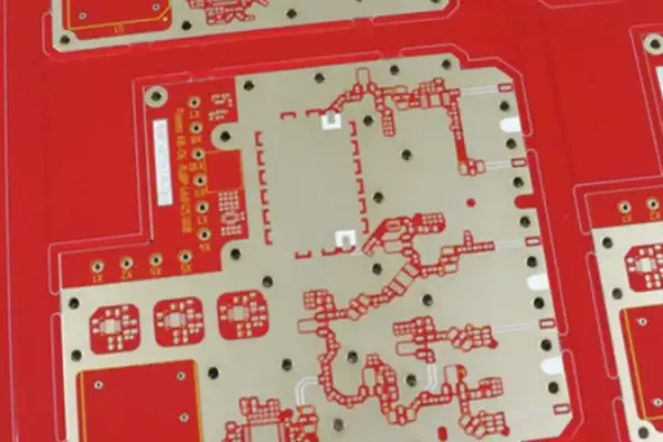
Why the Matrix Pixel Headlight Needed a Completely Different Copper Strategy
I used to think a headlight control board was just a simple circuit board, until I actually participated in a project myself and realized there’s far more depth to this than I imagined. People might think a headlight is just on-off, or at most a sequential turn signal at a fancier level. But actually, today’s smart headlights, especially lighting systems achieving complex projection and interaction, have core control-board designs that are a completely different-dimension challenge.
Take the project we were working on, for example — to achieve that fine, pixelated lighting effect, like projecting warning patterns on the ground or interacting with pedestrians via a light carpet, we needed to integrate a massive number of LED driver units on one board. This isn’t traditional single-channel control anymore — it’s a complex matrix control system. Every tiny LED pixel needs to be independently, precisely controlled — this places nearly demanding requirements on the PCB’s own carrying capacity and design precision. An ordinary circuit board simply can’t handle that kind of dense current channels and complex data flow.
At this point, board material selection becomes critical. We initially considered conventional FR-4 material, but simulation and preliminary testing found thermal dissipation and high-frequency signal integrity to be a big problem. Those densely arranged driver chips generate very concentrated heat during operation. We later turned our attention to aluminum substrate, what we commonly call aluminum-base PCB. Its metal base layer genuinely has good thermal performance, quickly conducting heat away, preventing local overheating from degrading or failing chip performance. However, aluminum substrate has its limitations too.
As our control logic grew increasingly complex — like implementing dynamic adaptive high-beam masking, needing to process camera data in real time and generate a corresponding lighting control matrix — ordinary aluminum substrate started feeling a bit inadequate for carrying multilayer, high-density fine circuitry. We had to seek out a more specialized partner — a heavy copper PCB supplier offering special processes.
Why do we need heavy copper? Because in this kind of high-density LED matrix drive scenario, “power” must be sufficiently strong and stable. Every trace needs to carry a continuous or instantaneous peak current far greater than conventional design, to drive a dense LED array. Ordinary copper thickness easily overheats or even burns out under long-term high-current operation. Heavy copper PCB, by thickening the conductive-layer copper foil, dramatically improves current-carrying capacity and thermal efficiency — equivalent to expanding and reinforcing the “blood vessels” of the entire lighting system.
This is far more than simply thickening one copper layer. It means the entire PCB manufacturing process, including etching, lamination, even drilling precision, needs to be readjusted. A reliable heavy copper PCB supplier must be able to precisely control the thickened copper layer’s uniformity and handle the resulting increased processing difficulty, ensuring the final board’s reliability and consistency. This is the foundation of foundations for the entire headlight system’s stable operation.
We also took quite a few detours in layout. In the earliest version, we routed digital signal lines and analog power lines fairly close together and parallel, and the result was, during high-frequency PWM dimming, the digital signal’s fast transitions severely interfered with the analog section’s voltage reference, causing visible flickering and unevenness in some LEDs.
We later completely restructured our layout strategy, strictly separating circuit regions of different natures. Especially for the matrix manager chip responsible for generating pixel-level control signals, we arranged layer upon layer of “guards” around it. A large number of decoupling capacitors were placed as close as possible to the chip’s pins, absorbing instantaneous current demand and stabilizing the power rail. High-speed data line routing was like a carefully choreographed formation, strictly controlling length difference, ensuring commands reach every driver unit simultaneously.
Throughout this whole process, my feeling was: designing an excellent headlight control PCB has long surpassed simple electrical-connection function. It’s more like performing a precision dance about power electronics, thermal management, signal integrity, and electromagnetic compatibility within an extremely limited space. Every component’s placement, every trace’s path, even every via’s position, directly affects whether the final headlight can light up precisely, stably, and impressively.
Why Solder Joint Reliability Matters as Much as EMC Compliance
I’ve always felt many people’s understanding of automotive circuit boards is a bit skewed. Everyone loves staring endlessly at complex EMC standards and deep theoretical analysis. Actually, this thing isn’t that mysterious. Having handled quite a few headlight control board design projects, I’ve noticed an interesting phenomenon: often the problem isn’t in theoretical calculation — it’s in the most basic material selection and physical structure.
Take thermal dissipation, for example — many people think aluminum substrate is all about fast heat dissipation, which is true, but the mechanical stability it brings is often overlooked. Especially in headlights needing to frequently switch high-power LEDs, the circuit board itself experiences thermal cycling — over time, ordinary FR4 material easily deforms or even develops microcracks, affecting solder-joint reliability. A good aluminum substrate provides solid support, dispersing thermal stress — its contribution to long-term stability might be greater than simply optimizing some filter circuit. For example, in city driving with large day-night temperature swings or frequent start-stop, aluminum substrate’s thermal expansion coefficient matches the LED chip better, dramatically reducing internal stress from material “tug-of-war,” avoiding solder-joint fatigue fracture. This gain from the base material is hard to compensate for through later circuit debugging.
On the power section, I’ve seen too many people focus all their attention on capacitor and inductor selection — that matters, of course. But I prefer spending more time at the layout stage considering how the actual current path can flow more smoothly. For example, reserving wide enough copper foil for the high-current path — sounds like common sense, right? But in practice, many designs, chasing compactness, make routing as intricate as a maze. At this point, finding a reliable heavy copper PCB supplier becomes especially critical. They can build a solid, thick copper layer letting high current pass smoothly, reducing extra heat and voltage fluctuation caused by trace impedance right at the source — a problem you can’t fix later by adding capacitors. Imagine power flowing from the interface to the chip, like water flowing through a pipe — a winding, narrow path inevitably causes turbulence and pressure drop. Using 2-ounce or even thicker copper foil is like widening the “water pipe,” significantly lowering current density — not only reducing temperature rise, but also improving response speed under instantaneous high current load.
Then there’s the test point, often treated as an afterthought. My habit is to reserve their position right when drawing the first draft, and choose the location carefully. You can’t place a test point next to a high-speed switching signal path — that’s basically installing a mini antenna on yourself, specifically broadcasting noise. It should be placed at the power input or regulated output — a relatively quiet spot — convenient for monitoring real power quality. Sometimes, to avoid affecting the main circuit’s performance, I’ll even isolate it with a very small series resistor, then add a picofarad-level capacitor to ground to filter high-frequency interference — only then is the measured data reliable. Specifically, this series resistor is usually chosen between 10 and 100 ohms — it doesn’t introduce significant measurement error, while effectively isolating the test probe’s capacitance from affecting the high-speed circuit. That small capacitor to ground acts like a “noise trap,” specifically absorbing high-frequency noise introduced or extracted by the probe.
As for the connecting wire between the headlight control board and the long string of LED light boards behind it, many people just treat it as a simple wire — actually, it’s a proper antenna. The longer the wire, the more pronounced its resonance at a specific frequency, and the stronger the radiated noise. My experience is: rather than racking your brain doing various shielding on the control board, it’s better to optimize the whole thing overall — placing the drive circuit as close to the load as possible, or simply adopting distributed small-power driver units to reduce the rate of current change on a single wire. Sometimes a simple physical structure change is far more effective than winding a coil half to death on the circuit board. For example, changing from a traditional centralized drive to placing a micro driver module near each light group, powered through a low-voltage DC bus — this way, what’s transmitted over long distance is stable DC, fundamentally eliminating the high-frequency current loop radiation problem.
Ultimately, designing a reliable vehicle lighting control board isn’t about following some perfect formula — it’s a continuous process of trade-offs. You need to find the most suitable balance point among thermal dissipation, mechanical strength, electrical performance, and cost — staring at waveforms in simulation software alone won’t reveal it — you need to think through the problem combined with actual manufacturing process and material characteristics. For example, when choosing a thermal adhesive or potting material, you need to look not just at thermal conductivity, but also at its curing stress, long-term aging performance, and compatibility with different metals — combined, these factors determine the final product’s real-world performance under bumps, high-low temperature, and humid, harsh environments.
Why Chasing a “Perfect” PWM Frequency Missed the Real Interference Source
I recently noticed an interesting phenomenon: many people, when discussing headlight control boards, always fixate on especially technical details. Actually, I think sometimes we might be overcomplicating simple things. Take a project I ran into last time — the client insisted we tune the PWM frequency to a specific range, saying it could avoid some radio interference. I tried it and found it’s not that absolute — the key is really how the whole system works together. For example, we eventually found the interference source mainly came from a USB charger next to the car’s cigarette lighter, not the radio band — adjusting PWM had minimal effect, but adding a simple ferrite bead at the control board’s power entry solved it.
I’ve seen quite a few headlight control board designs that, chasing so-called “perfect” parameters, routed extremely complex circuits, actually increasing the likelihood of problems. Do you know that sometimes the simplest approach is the most effective? Like adding a suitable resistor on a signal line, or adjusting a capacitor’s position, can solve a lot of mysterious interference problems. I had a project before that used quite ordinary aluminum substrate with some simple layout adjustments, and the result was actually better than designs using expensive material. Specifically, we moved the LED driver’s feedback signal line away from the power inductor and shortened its loop area — cost barely increased at all.
On material selection, I think a lot of people are somewhat overly superstitious about heavy copper boards now. It’s not that it’s bad — it depends on where specifically it’s used. In some places, ordinary-thickness copper board, combined with reasonable thermal design, is entirely sufficient. I’ve seen designs that, despite not having much power, insisted on using heavy copper board — cost went up but thermal performance barely improved. For example, a small module driving a 5W LED, using 2-ounce copper thickness with good layout, has temperature rise fully under control — blindly jumping to 4-ounce not only makes the board hard to manufacture, it’s also a challenge for via process.
On the common-mode interference issue, I think people might be a bit overly worried. Of course I’m not saying it doesn’t matter — I’m saying we can handle it more cleverly. For example, paying a bit of attention to signal-line and power-line routing direction during layout often avoids most problems. There’s no need to add a pile of filter components everywhere — that increases cost and might bring new problems. For example, routing sensitive low-voltage signal lines on a middle layer of the board, shielded by power and ground layers, is far more economical and reliable than adding a common-mode inductor on every single wire.
I remember once testing a headlight control board and finding a certain pin’s signal especially unstable. At the time, the team wanted to add a complex filter circuit, but I suggested first checking whether the ground path was short and direct enough — after adjusting the grounding method, the problem resolved. You see, sometimes the problem is that simple. That pin was the MCU’s ADC input, and its ground reference originally connected to the main ground through a long, thin path — we just added a via directly to the main ground layer, and noise dropped significantly.
I think the longer you work in this field, the more you understand a principle: good design isn’t stacking the best components — it’s finding the most suitable balance point. Every project has its own particularities — copying someone else’s parameters or scheme often doesn’t work. You need to adjust and experiment based on actual conditions, sometimes even needing to break some so-called “industry conventions.” Like in harsh vibration environments, sometimes a direct, reliable solder joint beats a plug-in connector, even if “convention” recommends using a connector.
I find myself wanting to laugh a bit now when I see articles making PCB design sound so mysterious. There aren’t that many secrets — it’s just connecting what needs connecting, and isolating what needs isolating. Experience matters, of course, but experience isn’t memorized parameters — it’s knowing what method to use in what situation. For example, the “3W rule” is experience, but knowing when it’s acceptable to reasonably violate it for density is even more valuable experience.
Have you noticed that many product manuals’ technical parameters are actually data under the most ideal conditions? Real-world application can never reach that condition, so designing strictly according to those parameters can actually cause problems. I prefer to gradually adjust during actual testing, finding the point most suited to the current project. Like an LDO chip — the datasheet states a maximum output current of 500mA, but in your compact space and high-temperature environment, it might become unstable above 300mA — at that point you need to test it directly.
Ultimately, this line of work still relies on practice, on hands-on trial. Reading many theoretical articles is less useful than doing one hands-on test yourself. What do you think?
Why the Board That Overheated Was Actually Missing a Thermal Path, Not Copper
I recently talked with a friend who works on automotive lighting fixtures, and he mentioned their factory’s newest batch of samples had problems again — the problem was exactly on the control board. This is quite interesting and got me thinking a lot. We always assume soldering a bunch of LED beads onto a board settles everything, but actually, the PCB carrying them is the real behind-the-scenes hero determining success or failure.
Think about it — a car’s lighting system is getting increasingly complex now, no longer just simply lighting the road. Daytime running lights, turn signals, ambient lights, and various smart interactive lighting all need a “brain” to precisely control on/off timing. This is the core mission of a Vehicle Lighting Control PCB. This board must stably issue commands in the car’s various bumps, vibration, and hot-cold alternating environment. If it itself gets “heatstroke” or “catches a cold,” the lighting will definitely malfunction.
So many people jump straight into thinking about what advanced chip and control algorithm to use. That matters, of course, but I’ve found a more basic question often gets overlooked: can this board itself withstand it? Especially on thermal dissipation. I’ve seen quite a few design drawings where engineers put a lot of effort into optimizing the circuit, but chose the most ordinary FR4 board material, unwilling to add copper thickness. The result? Sample testing showed great lighting effect, but after a few thousand kilometers installed on a car, brightness starts visibly decaying. The problem is heat not escaping, literally “smothering” the LED to death.
At this point, finding a reliable heavy copper PCB supplier becomes especially critical. What I mean by “heavy copper” isn’t simply adding a layer casually. You need to consider current-carrying capacity and its ability, as a “highway,” to conduct heat away from under the chip. Some high-power headlight modules generate astonishing heat during operation — ordinary 1-ounce copper foil simply isn’t enough, possibly needing 2-ounce or even 3-ounce-plus thick copper. These copper layers are like building multiple wide main roads for heat, letting it spread more quickly across the entire board area, then dissipate into the air through structural components.
Of course, FR4 material itself has its limits — its thermal performance is what it is. When heat gets large enough, you need to consider switching paths. This is why, in some headlight positions with extremely demanding thermal requirements, like certain high-brightness main lighting units, designers turn to Aluminum-Based PCB. Aluminum itself is an excellent heat sink, able to directly “absorb” heat generated by the chip — far more efficient than conducting through FR4. Though cost goes up, for guaranteeing LED long life and high reliability, this money is often well spent.
This actually raises a fairly realistic trade-off. You can’t use the most expensive metal substrate on every board — the cost is unbearable. Good design should be tiered. For the control-logic section, where chips don’t generate much heat, high-quality FR4 with appropriate copper thickness might be sufficient. For the section directly driving high-current LEDs, local reinforcement might be needed, even considering metal substrate. This tests your precise understanding of the entire system’s thermal distribution, not simply piling on material.
Ultimately, a good vehicle headlight PCB isn’t just a circuit carrier — it’s more like part of a precision thermal-dissipation system. From material selection to copper-thickness design to fit with the final fixture housing, every detail affects whether that tiny LED bead can keep glowing stably and steadily. Next time you see a car’s lights looking beautiful and even, maybe think about the unremarkable board behind it, quietly enduring the test of high temperature and excellently completing its job.
Why Ordinary FR4 With Good Layout Can Beat Aluminum Substrate
I’ve always felt the thermal dissipation problem for headlight control boards is overcomplicated. Many people, the moment high-power LED drive comes up, go straight to aluminum substrate, as if you can’t build a product without it. Actually, often, ordinary FR4 board material, if designed properly, can fully withstand it. I worked on a project that used a conventional double-sided board — copper thickness increased to 2 ounces, with a large enough copper-fill area around the LED and reasonably distributed thermal vias — and final temperature rise was controlled quite well.
The key isn’t how expensive a material or how complex a structure you use — it’s whether you genuinely understand how heat travels. Heat leaves the LED’s pad, first conducts to the PCB’s copper layer, then spreads across the entire board, and finally dissipates into the air or the housing. If you’re just blindly stacking metal while overlooking the thermal-resistance bottleneck in between, the effect might actually be worse than a carefully designed ordinary board. For example, sometimes if the thermal pad between the pad and the heatsink is chosen poorly, with an uneven contact surface or air bubbles, thermal conductivity efficiency drops dramatically — however good the board material used earlier, it’s wasted.
On the topic of thermal via design — this is genuinely an easy place to trip up. I’ve seen quite a few engineers like drilling dense via arrays under heat-generating components, thinking this “leaks” heat downward. But there’s a detail here — if these vias’ surfaces aren’t handled properly, like not resin-plugged or capped, molten solder paste during soldering easily gets sucked into the hole, resulting in the solder joint actually having no solder. This not only affects soldering reliability, but excessive voids also hinder thermal conduction. My experience is: for these critical thermal channels, either do copper-fill treatment to make it a solid thermal column, or strictly control hole diameter and spacing, ensuring pad flatness.
Of course, I’m not saying aluminum substrate is useless. In some extreme cases, like extremely constrained space or truly excessive power density, aluminum substrate, relying on its metal core’s high thermal conductivity, is genuinely a better choice. A good aluminum substrate supplier will tell you they’re not just selling you a board — more importantly, they can recommend suitable insulation-layer material, thickness, and copper-foil spec combinations based on your specific application scenario. Because aluminum itself conducts electricity, the thermal conductivity of that middle insulating dielectric layer becomes the key factor determining overall thermal dissipation capability.
I think looking at thermal management on a PCB should be viewed as a systems engineering effort. From LED chip package type, to PCB pad design and routing layout, to housing material and airflow channel design — every link interlocks. Sometimes, rather than putting all the pressure on the PCB alone, it’s better to slightly adjust the surrounding structural design — the effect might be better and cost lower. After all, our goal is to make the product work stably and reliably, not to use technology for technology’s sake.
Why a Ten-Year Lifespan Requirement Challenges Physics Itself
Every time I see a car’s headlights turn on, I think about how many engineers must be scratching their heads behind the scenes. We always think a headlight is just a matter of swapping a bulb — actually, it’s far more than that. Take a project I worked on recently, for example — the client wanted a headlight control board that could work stably for ten years. This sounds like a fairly reasonable requirement, right? But once you actually start building it, you find it’s practically challenging the laws of physics.
You first need to think about what material is most suitable for the board itself. Many people think aluminum substrate has good thermal dissipation and use it for everything — that’s not necessarily right. Aluminum does conduct heat quickly, but in some scenarios requiring withstanding drastic temperature changes, its thermal expansion coefficient might cause trouble. I’ve seen cases where, because of improper material selection, solder joints on the board cracked with continued use. At this point you need to think about whether special material should be used — like board materials specifically designed for high-temperature environments — more expensive, but saves countless later headaches. For example, in some high-end applications, engineers use ceramic substrate or composite metal substrate — these materials maintain more stable mechanical performance under extreme temperature cycling, avoiding microcracks caused by thermal stress. The material surface coating process matters greatly too — for instance, conformal coating selection must consider its temperature range and adhesion, or in humid salt-spray environments, coating peeling directly causes short circuits.
On temperature change — this is really the most tormenting part. A headlight’s operating environment is too extreme — the inside of the fixture housing can reach seventy or eighty degrees under summer sun exposure, and drop to several dozen degrees below zero in winter. This repeated tossing is a slow-motion murder for electronic components. We’ve run tests — ordinary circuit boards might not survive past two years under these conditions before all kinds of strange problems appear, like capacitor failure or chip performance degradation. Looking more closely, sudden temperature change causes shear stress at different material interfaces — for example, solder balls between the chip package and PCB might fatigue and fracture after hundreds of thermal cycles. So accelerated life testing often uses thermal shock chambers, rapidly switching between -40°C and 125°C, simulating years of actual use, to screen out design weaknesses.
Another point many people might not notice is transient voltage shock. A vehicle’s power system isn’t as stable as we imagine while running — for instance, when the engine starts, or certain electrical equipment suddenly shuts off, an instantaneous high-voltage pulse is generated. This shock is simply catastrophic for sensitive circuits. So when designing the power section, we must add sufficient protection measures, like selecting a suitable TVS diode to absorb this energy, or a surge could destroy the entire control board. In actual testing, we’ve captured with an oscilloscope voltage spikes exceeding 60V at the instant of starting — far beyond the 12V system’s normal state. So beyond a TVS diode, we typically also pair it with an LC filter network and a voltage regulator chip, forming multi-stage protection. Even connector selection needs to consider contact resistance, avoiding arcing that worsens interference when large current passes through.
I remember once testing where we installed a finished sample on a car for road testing, and found the headlight would mysteriously flicker under specific conditions. After a lot of digging, we found it was because a component’s layout wasn’t reasonable enough, causing poor contact under mechanical vibration. This lesson taught me that PCB design isn’t just drawing lines — you also need to consider its various force-bearing conditions in the real environment. For example, a heavier electrolytic capacitor, if not close to the board’s support point, might have its leads fracture from mechanical fatigue under long-term vibration on bumpy roads. So layout often uses finite element analysis to simulate vibration modes, adding adhesive or clip fixation at critical points. Also, the connector’s insertion direction and locking mechanism need to match the vehicle’s installation angle, preventing loosening from gravity or vibration.
Load capacity is also a question needing careful weighing — some designers, chasing performance, pile on every function, resulting in the board staying under long-term high load, naturally shortening lifespan; overly conservative design limits product feature realization. Finding that balance point requires a large amount of experiment and data analysis — it’s not solvable purely through theoretical calculation. For example, in an LED constant-current circuit, if output current is set at 95% of the chip’s nominal maximum, though brightness increases, junction temperature rises sharply, potentially cutting mean time between failures in half. So we often use thermal simulation software to plot temperature maps, and per derating design guidelines, keep actual usage power below 70% of the component’s rated value, while reserving a thermal path — like using the fixture housing’s inner wall as a dissipation surface.
Actually, the longer you work in this field, the more you find yourself gradually becoming a generalist — needing to understand electronic principles, material characteristics, and manufacturing process. Sometimes, to solve one problem, you might need to rethink the entire chain from chemical materials to mechanical structure — this cross-disciplinary challenge is the most interesting part. For example, to improve waterproof performance, we once worked with chemical engineers to develop custom sealant, needing both enough elasticity to accommodate thermal expansion and UV-aging resistance. Or automated production’s soldering process parameters need adjustment based on different PCB surface finishes (like immersion gold or OSP), or solder-joint reliability is affected. This kind of deep collaboration often sparks unexpected innovative solutions.
Why a Passed Certification Doesn’t Mean a Reliable Board
I’ve always felt many people’s understanding of automotive circuit boards is a bit off. Everyone loves hanging automotive-grade certification on their lips, as if passing those tests settles everything, but I think what genuinely tests a board’s quality often hides in production details nobody pays attention to.
Take a headlight control board, for example — it’s trendy now to make it very compact, with functions growing increasingly complex. This means components are packed especially densely, and traces are as thin as hair. Think about it — when the car bumps on a pothole-riddled road, will these thin lines crack from vibration? Or when temperature swings hot and cold, will different materials’ different expansion coefficients pull solder joints apart? These questions can’t be solved by a certification report alone.
I’ve seen some manufacturers cut corners on material selection to save cost. They think as long as the final product passes testing, it doesn’t matter what material was used in between. This mindset is especially dangerous. For example, a thick-copper board needing to carry large current — if the copper foil purity isn’t high enough, or the lamination process isn’t up to par, it might delaminate from heat before long, and the entire headlight system could fail.
There’s also the now-popular aluminum substrate — many people blindly choose it thinking it has good thermal dissipation. But aluminum substrate and ordinary FR4 material have very different expansion rates — if your designed circuit board has both ordinary components and heat-generating power devices, using aluminum substrate entirely might actually cause soldering problems from uneven thermal stress. Good design should mix materials based on different area needs, but this requires the engineer to have deep understanding of both material and process. For example, you can locally use aluminum substrate or embed a copper block beneath a high-power LED driver chip, while the control-signal section still uses conventional board material — this requires precise lamination and interconnect technology, not simple piecing together.
On BGA packaging, I’ve found quite a few people overlook the underfill step. Especially for chips used in this headlight-control environment, vibration and temperature change are everyday occurrences. A BGA solder ball without underfill protection is essentially a ticking time bomb — it might fracture from fatigue any day. Underfill not only disperses stress, it also prevents moisture intrusion and tin-whisker growth — its flowability, cure shrinkage, and glass-transition-temperature selection all need to match chip size and substrate material — a process window requiring repeated validation.
Actually, finding a reliable PCB supplier matters more than anything. A good supplier will analyze design risk points with you, rather than just starting production once you send the file. They’ll tell you which designs are prone to problems in actual production, and which material combinations are more reliable. For example, they might suggest using a more precise impedance-control structure for high-frequency signal lines, or remind you to avoid placing fragile ceramic capacitors in easily-bent areas.
A supplier I worked with left a deep impression on me. They wouldn’t just cater to a client’s demand to lower the quote — they’d explain in detail why certain processes must be done this way for the cost to make sense. For example, when doing thick-copper board, they strictly control etching parameters to ensure trace edges are smooth without burrs; when laminating multilayer boards, they use a special preheat program to reduce internal stress. These details might sound trivial, but they have a huge impact on final product reliability. They’ll even run thermomechanical analysis on every batch of base material, to predict its performance under temperature cycling — far beyond standard testing scope.
Automotive electronics and consumer electronics are completely different games — you can’t apply the fast-iteration mindset from phones to automotive products. A car might run on the road for over a decade, going through all kinds of extreme environments — so every component behind it must withstand the test of time. This isn’t as simple as passing a few certification tests — it concerns the entire production system’s quality stability. From raw material incoming inspection, to etching-solution concentration management, to cleanroom particle control — every tiny variable could become the trigger for the product’s failure ten years down the line.
I think there’s a somewhat unhealthy tendency in the industry right now — being overly superstitious about various standards and certifications. Of course these standards matter, but they’re just the minimum bar — genuine quality comes from strict control over every production link and deep understanding of material characteristics — that’s the real key to making a good product. For example, AEC-Q102 certification requires LED devices to pass a series of tests, but doesn’t specify the UV-aging resistance of the potting compound around it after soldering onto the board — and that’s exactly the key to a headlight staying clear and not yellowing long-term.
Why a Board’s Real Test Begins Under the Hood, Not in the Lab
I’ve always felt many people’s understanding of PCBs is too narrow. They always view the circuit board as a passive carrier — as long as the traces are connected, it’s fine. This mindset actually causes a lot of trouble.
I’ve worked on quite a few automotive-industry cases. Once, a headlight control module kept having problems, and tracing it back, the root cause surprisingly wasn’t in the chip, but in that seemingly simple Vehicle Lighting Control PCB. The designer only considered functional realization, overlooking the subtle physical changes in the actual working environment.
Temperature changes cause materials to expand and contract, and vibration brings sustained stress. Combined, these factors are a long-term test for the circuit, especially thick-copper traces carrying high current. For example, near the engine bay, temperature might cycle between below zero and over a hundred degrees Celsius — this thermal cycling causes different materials (copper, FR-4 substrate, solder) to expand at different rates, generating shear stress, potentially causing solder-joint cracks or conductor breaks over time.
On the topic of thick copper, many people’s first reaction is to find a Heavy Copper PCB Supplier capable of it. That’s correct, but the supplier’s technical approach and process understanding are what actually separate the good from the mediocre. A good supplier won’t just give you “thicker copper” — they’ll discuss current load, thermal management scheme with you, even anticipate potential material fatigue after long-term operation. For example, they might suggest a stepped copper-thickness design, locally thickening at connectors or power-device pins rather than evenly thickening the entire board — this meets current-carrying needs while optimizing cost and weight.
This reminds me of another common misconception: relying on adding a fan or switching material to solve thermal problems.
Indeed, many people immediately think of Aluminum-Based PCB the moment heat comes up. Aluminum substrate’s good thermal conductivity is a fact.
But it’s not a cure-all.
You first need to think clearly about where the heat comes from and where it goes.
Sometimes heat concentrates in a specific area rather than distributing evenly; sometimes the problem isn’t thermal conductivity but insufficient thermal mass; and sometimes the mechanical mounting method itself becomes the thermal-dissipation bottleneck. For example, in an LED driver board where the heat source is a MOSFET — if you simply switch to aluminum substrate without optimizing the interface contact with the heatsink (like ignoring thermal-paste application uniformity or mounting pressure), heat still can’t be effectively conducted out.
Blindly switching materials might spend more money without solving the fundamental problem, even bringing new problems, like increased cost or excess weight.
Take solder mask, for another example.
It’s not just for looks or oxidation prevention — it’s more than that.
Good solder mask process protects the traces from environmental attack, and also plays a critical insulation and protection role during assembly. For example, in high-density design, the solder-mask layer prevents bridging between fine-pitch pads during soldering.
I’ve seen some products test all normal in the lab but develop all kinds of mysterious faults once in the customer’s hands — later found to be because the solder-mask layer underwent subtle change under specific temperature-humidity conditions, affecting nearby circuit performance. For example, in a coastal high-salt-spray environment, inferior or unevenly-thick solder mask might age and crack prematurely, causing copper-foil corrosion or reduced insulation resistance.
So you see, PCB manufacturing has never been a series of isolated processes.
From design and material selection to process control to final testing — every link interlocks. For example, material’s coefficient of thermal expansion (CTE) matching affects drilling and lamination process, in turn affecting final reliability.
On testing — many factories today can do basic continuity checks, but what genuinely finds problems isn’t just looking at “connected or not” — it’s looking at “how good.”
Electrical performance consistency and long-term reliability are what separate high-end applications from ordinary ones. For example, beyond continuity, you should also test whether characteristic impedance is within tolerance, insulation strength under high voltage, and run thermal cycling and vibration testing to simulate aging.
Especially in a field like automotive electronics with extremely high safety requirements, one testing oversight could mean enormous risk.
Ultimately, making a good PCB requires more than meeting technical parameters — it requires a systematic way of thinking. You need to understand what environment this board will work in in the future, what challenges it will face, and prepare for those challenges right from the design stage — this is more meaningful than simply chasing a single metric, and better able to produce a genuinely reliable product.
Why a Delamination Gap Inside an Aluminum Substrate Caused Flicker
I recently found an interesting phenomenon — many people, when discussing headlight control, always love steering the topic toward impressive-sounding technical terms, as if you’re not professional enough without piling on a few terms. But after tinkering with a few boards myself, I feel things might not be that complicated.
The first headlight control board I encountered was pulled from an old car, given to me by a friend. The back of that board was covered in thick traces — clearly using a heavy-copper process, and I wondered at the time why it had to be handled this way. I later figured out it has little to do with thermal dissipation — it’s more about large-current stability, especially during frequent switching instants where current shock is significant. Ordinary traces easily overheat and age, even melt, in this environment, while thick copper provides lower impedance and better thermal mass. This reminds me that when I previously found a supplier to prototype, they repeatedly emphasized their thick copper boards could handle greater sustained current — looking back now, that wasn’t just talk. For example, when driving a high beam or LED matrix, instantaneous startup current might reach several times the steady-state value — thick copper design effectively reduces voltage drop, ensuring stable, flicker-free light brightness — something an ordinary PCB struggles to guarantee.
On thermal dissipation, many people immediately think of aluminum substrate. I used to be superstitious about this too, thinking that once you use aluminum, temperature problems are solved. But once I helped someone repair a faulty LED driver module, the symptom being flickering light. Opening it up, the problem was exactly in the aluminum substrate. There was a visibly separated gap between the insulation layer and the aluminum material, and moisture had crept in, directly corroding and shorting the circuit. This experience taught me deeply: the material itself has advantages, but if the bonding process isn’t up to par, or it endures long-term thermal cycling, even the best base material can become a hidden risk. So now, when I look at aluminum substrate, I pay more attention to its overall structure and process details, not just whether it’s “aluminum.” For example, I check its insulation layer’s thermal conductivity, dielectric strength, and whether the aluminum layer’s anodizing treatment is adequate — these details often determine its lifespan in the engine bay’s high-temperature, high-humidity environment.
As for BGA packaging, I think its application in automotive electronics is somewhat overhyped. Of course its high-integration advantage is clear, saving a lot of space. But I’ve seen more than once cases where an entire control unit failed because of BGA solder-joint problems. Especially in environments with dramatic temperature swings, like near a headlight — if the PCB material and BGA chip’s own thermal expansion coefficients don’t match well, after countless hot-cold cycles, those tiny solder balls might develop internal cracks. This kind of failure is often sporadic, extremely headache-inducing to troubleshoot, sometimes even requiring cross-section analysis to locate the root cause. Actually, some designs use underfill adhesive to reinforce solder joints, but this increases repair difficulty and cost, forming a dilemma.
Another commonly overlooked component is the inductor. It’s common in power-conversion circuits, but improper selection or layout can bring real trouble — beyond the well-known electromagnetic interference issue, I’ve run into more specific situations. In a buck circuit, that inductor emitted a faint whining sound under a specific load — though it didn’t affect function, it was especially annoying in a quiet cabin, and long-term vibration also showed fatigue signs in the copper foil around its pad. We later adjusted the circuit’s operating mode to avoid that human-ear-sensitive frequency range, and reinforced it with adhesive to fully resolve it. This phenomenon is especially noticeable when the switching frequency falls within the audible range (usually a few hundred Hz to a few kHz), involving the inductor’s core material, winding process, and the circuit’s feedback-loop stability.
So looking back, whether headlight control or other in-vehicle electronics PCB design, I don’t think you can view a single component or process — like thick copper or aluminum substrate — in isolation. It’s more like a systems engineering effort, requiring comprehensive consideration of electrical performance, mechanical structure, environmental adaptability, and long-term reliability — sometimes chasing one extreme parameter might plant a landmine elsewhere. Genuinely reliable design usually finds a balance point among various constraints, not simply piling on so-called “high-end” material. This might be where engineering practice differs from theory manuals — after all, the thing needs to run on a car, not sit displayed in a lab. For example, a perfect thermal solution might bring uncontrolled weight or cost, while extreme lightweighting might sacrifice vibration resistance — this requires the engineer to continuously iterate and weigh through simulation, testing, and real-road feedback.
Why the Interface Between Layers, Not the Copper Spec Sheet, Decided Reliability
I sometimes feel people treat the PCB as a purely hardware component. Especially in fields like vehicle lighting control, many people open the conversation talking about thermal dissipation, impedance, material strength, as if filling in these parameter tables settles everything. But I look at the problem a bit differently.
In a project I handled, this happened: a headlight module started showing sporadic signal disruption late in testing — extremely frustrating to track down. It eventually turned out the problem was neither the main control chip nor the LED itself — the root cause was surprisingly in an unremarkable aluminum substrate. At the time, chasing extreme thermal performance, we chose a supplier claiming their aluminum substrate had extremely high thermal conductivity, but later found their bonding process between the metal base layer and insulating dielectric layer had a flaw, causing peel strength to decay rapidly under actual high-low temperature cycling. This directly affected the stability of the precision traces above, and the signal got lost in this kind of microscopic deformation.
This experience made me realize: when discussing a PCB, especially a critical component like a Vehicle Lighting Control PCB, you can’t just look at its static parameter sheet. It works inside a dynamic, vibration-filled metal box — you need to consider what it will go through across its entire lifecycle. You find a Heavy Copper PCB Supplier, and of course they’ll show you copper-thickness parameters, but if they haven’t put enough process thought into interlayer bonding strength, however thick the copper foil, it might slowly separate at some stress-concentration point.
So my view is: the future direction might not be blindly chasing extremes on some parameter, like making the board material thinner or heat conduction faster. The real challenge is how to let these different needs — electrical performance, mechanical strength, thermal management — coexist harmoniously within a limited space, and coexist stably for over ten years. This sounds like empty talk, but a lot of designs fail exactly on this point.
For example, the now-popular software-defined headlight feature is growing increasingly complex, meaning denser traces on the PCB, more components, and more uneven heat generation. You use a high-end aluminum substrate to dissipate heat for the high-power LED area, but if internal stress builds up over time in other areas’ ordinary FR4 material due to mismatched thermal expansion coefficient, will it affect the whole board’s flatness? Could those fine signal lines get damaged as a result? None of these problems can be solved by a single material — it tests your understanding of how the entire system coordinates under various “pressures.”
I think the industry is sometimes too enthusiastic about chasing new terms, overlooking these basic but critical things. A reliable PCB isn’t simply piled together from the most expensive materials — it comes from deep understanding and strict control over every connection point, every lamination, every etching step. Ultimately, it’s an art of balance, needing to find a solid foothold among cost, performance, and long-term reliability.
This might not be cool, but it determines whether your design stays merely a showpiece on paper, or becomes a reliable product that can truly withstand countless days and nights on the road.
What actually makes a long-term PCB supply chain partnership work — shared
Practical, experience-based strategies for how to reduce PCB procurement risks — from
Real factory-floor lessons on how to optimize a PCB manufacturing process —
- Pienten ja keskisuurten erien tuotannon asiantuntija
- Korkean tarkkuuden piirilevyjen valmistus ja automatisoitu kokoonpano
- Luotettava kumppani OEM/ODM elektroniikkaprojekteihin
Aukioloajat: (ma-la) klo 9:00-18:30.
Get quote, solution or any question, Andre always here to help