

Automotive Rain Sensor PCB: How Optical Paths, Potting, and Fabrication Quality Decide Field Performance
Do you think a rain sensor is just a simple circuit board?
Why PCB Fabrication, Not Circuit Design, Is the Real Risk in Medical Laser Hardware
A few years ago I took on a project redesigning the main board for a dermatology laser device. At the time, my understanding of a Medical Laser Equipment PCB was still stuck at the level of an ordinary digital circuit — I figured it was just drawing a board and running a laser diode. It was only once I actually got into it that I realized the waters here run far deeper than expected.
The biggest pitfall was not the circuit design itself — it was finding the right board shop. A laser device’s main control board typically has to carry large current pulses while also cramming control signals and the power loop into a very small footprint, which forces you toward high-density interconnect boards. An ordinary double-sided board simply cannot handle it — interlayer withstand voltage and thermal dissipation are both problematic. The first time I prototyped, I used a shop that normally builds ordinary consumer electronics boards, and the moment the laser fired on the finished board, ground-bounce noise completely swamped the sensor signals, falsely triggering the entire interlock loop — the machine was simply unusable. It was only afterward that I learned this kind of board requires an HDI PCB manufacturer who genuinely understands laser circuit characteristics — not just any HDI PCB supplier willing to take the order.
During that period, I went through no fewer than five suppliers before discovering that many shops advertising HDI capability could really only laminate a few passes of laser-drilled blind vias, with essentially zero process experience in heavy copper and thermal copper blocks. The pulse-driven MOSFETs and storage capacitors inside a laser device generate enormous heat — if copper is not thick enough or the thermal path is poorly designed, the board will start delaminating within a few months. One HDI PCB supplier actually asked me whether we could move the laser driver section onto a separate aluminum substrate — I did not know whether to laugh or cry; the whole device is only so big, where would that extra space come from?
I later spoke with a German engineer specializing in medical laser modules, and he made a point that stuck with me: a Laser PCB is not an ordinary circuit board — it is itself part of the safety system. Think about it: if a surgical laser goes out of control, that is a direct threat to life, so the multiple independent interlock loops on the board — including hardware interlocks and a software watchdog — must be physically isolated from each other. This requires thinking through the stack-up at the design stage: which signals absolutely cannot run adjacent on the same layer, and which high-voltage regions require isolation slots. At an HDI supplier, simply saying “build to the drawing” is not enough — they need to genuinely understand the IEC 60601 series requirements for creepage distance and electrical clearance, so they can proactively help you avoid process risks while building the board.
There is another point many people overlook — the impact of solder mask and surface finish on a laser system. One of our prototype units, during EMC testing, could not suppress radiated emissions no matter what we tried. It turned out that a particular batch of boards had a solder mask with an off-target dielectric constant, which shifted the microstrip line impedance, and the resulting pulse waveform overshoot literally doubled. We later switched to an HDI PCB manufacturer who specifically configures high-frequency board material and double-sided solder mask processes for medical laser customers, and the problem was finally resolved completely. From that point on, I never again treated the PCB as an ordinary outsourced component — I started managing it as a core component in its own right.
Looking back, when building medical laser equipment, selecting the right PCB manufacturer matters more than selecting the main control chip. Everyone has access to buy the same chip, but a genuine, stable supplier of HDI boards that meet medical laser requirements is genuinely rare. Now, when I evaluate suppliers, I do not care how many laser application case studies their brochure lists — I ask directly whether their factory has built heavy copper plus laser blind via boards before, whether they can provide withstand-voltage test reports, and whether they even know about the ionic contamination limits for medical boards. Ask these questions, and more than eighty percent of HDI PCB suppliers start hemming and hawing — the few who remain are the ones genuinely worth partnering with.
Real-World Failures: EMC, Isolation, and Why Consumer-Grade HDI Fails Medical Standards
I have worked with several teams building medical laser equipment, and I have found that what trips them up most often is not the laser itself — it is that unassuming circuit board. Many people, when choosing an HDI PCB supplier, still apply the consumer-electronics playbook, thinking that as long as the stack-up hits spec and trace width and spacing route cleanly, that is enough. But medical laser equipment squeezes high voltage, high-frequency pulses, and weak biological-signal acquisition into a single compact space — if the HDI PCB manufacturer lacks experience with medical-grade laser boards, the resulting board will very likely fail radiated emission and conducted immunity testing under IEC 60601-1-2. The most absurd case I ever saw was a four-layer board for a laser lithotripsy device where, because the laser driver loop and the physiological signal amplifier section had no stepped shielding isolation, every time the laser pulsed, the adjacent ECG acquisition channel would jump right along with it, ruining the whole waveform. We eventually had to redesign the board as second-order HDI, using laser-drilled blind vias to bury critical signals in an inner layer, sandwiching in a complete copper shield in the middle, before finally suppressing the interference. What this demonstrates is that medical laser equipment PCB design is not simply about routing traces correctly — it requires thinking through high-voltage safety spacing, creepage distance, and dual-patient-protection physical isolation right from the stack-up stage. So-called 2 MOPP insulation cannot be achieved just by painting on a final layer of conformal coating — it has to be embodied in the actual, physical distance between copper and copper, and between via and via. And since the laser’s cooling loop carries high voltage, even a small amount of moisture absorption in the board can trigger CAF growth and cause isolation failure. So when I recommend a supplier, I always ask whether they have built medical laser cases before, whether they can provide a consistency report on cross-sectioned, copper-filled laser blind vias, and whether the dielectric material is a genuinely low-water-absorption, high-CTI grade. An ordinary consumer-electronics or industrial-laser HDI PCB manufacturer will never take this seriously — but on a medical device, it is exactly what determines whether you pass FDA and MDR review.
Anyone who has built a complete medical laser device knows that PCB fabrication was never as simple as just finding a board shop and prototyping. On an early project, the laser driver board kept burning MOSFETs, and after tracing it all the way down, we found the high-voltage creepage distance had been left too small — once the board absorbed a bit of moisture, it would arc directly. That was when I truly understood that the insulation coordination tables in IEC 60601-1 are not there just to scare you. The circuit boards inside medical laser equipment, especially the ones carrying high-voltage energy storage and pulse discharge, are essentially energy-management units — applying ordinary industrial-board standards to them is asking for trouble sooner or later.
Later, a handheld laser therapy device forced us into using an eight-layer, second-order HDI board due to structural constraints, running both large current pulses and faint photodetector signals on the same board — the slightest layout misstep and the noise floor would rise unacceptably. Finding a reliable HDI PCB manufacturer was critical — not just in terms of how many layers they could laminate, but whether they could understand why the copper foil near the laser cavity needed such an unusual shape, and whether they would accept your requirement that no solder mask bridge be present around the laser pad, since outgassing could contaminate the optical elements. Among the suppliers I dealt with, genuinely few HDI PCB suppliers truly grasped this logic — maybe two out of ten.
Electromagnetic compatibility is its own headache. A Medical Laser Equipment PCB carries transient currents of several dozen amps alongside nanosecond-level switching edges, and once you look up IEC 60601-1-2, the radiated emission limits are far stricter than for industrial equipment. Once, during a 3-meter anechoic chamber test, radiated emissions exceeded the limit by over ten dB near 300MHz — it turned out that copper on the laser driver loop was forming an imperfect resonant cavity; only after changing board material and adjusting the stack-up did the emissions come down. Reading the standard is only step one — actually translating CISPR 11’s limits into board-level design decisions is the truly grueling part.
The upside of the IEC 60601 series is that it forces you to examine every PCB from a risk-management perspective. Take laser safety interlocks, for example — IEC 60825 requires hardware redundancy, and some designs place two independent feedback loops directly on the board so that, if optical power becomes abnormal, the hardware cuts off the pump source directly without waiting for the MCU to react. This kind of design pushes cost up considerably, but looking back, once a medical laser loses control of its output, the consequences are not something a repair can fix. So now, when I evaluate a supplier, I do not start with price — I ask directly whether they have built a project corresponding to IEC 60601-2-22’s laser-specific requirements. If they respond with “what is that,” the conversation is basically over.
Another easily overlooked factor is environmental reliability. Medical laser equipment is often wheeled around operating rooms, subject to sharp temperature and humidity swings, and some units even need to work with low-temperature spray cooling. Tests in the IEC 60068 series — alternating damp heat, thermal shock — are a genuine test of a PCB’s CAF growth and solder-joint reliability. I have seen boards fail an 85°C/85%RH biased humidity test because residual copper powder inside the inner layers reduced insulation resistance — a problem you cannot catch with flying-probe testing; it can only be controlled through the HDI PCB manufacturer’s lamination process and cleanliness standards.
At the end of the day, for medical laser hardware, the PCB is no longer just a connection carrier — it is part of the safety architecture. When you choose a supplier, you are essentially choosing a partner capable of weaving IEC 60601 clauses, the physical characteristics of laser light, and board material supply-chain stability all into their own manufacturing process. Every trace and every isolation slot on that finished board represents a double compression of both standards knowledge and engineering experience.
The more time I have spent on medical laser equipment over the years, the more I believe a reliable PCB is the true operator behind the scenes. Many people assume that as long as the laser diode driver is powerful, the job is done — but from high-voltage conversion down to picosecond-level pulse response, it all comes down to the artistry of the traces on the board. I have worked with several HDI PCB manufacturers claiming to do high-multilayer mixed lamination, but very few could actually withstand the hard logic demanded by an interlock circuit. Interlocking is not as simple as wiring up an emergency stop — from fiber-insertion detection, water-flow sensors, to housing microswitches, every single signal has to feed directly into hardware logic, completely bypassing software, because any delay could let the laser fire when it should not. During layout, how these interlock signal lines are isolated from the power loop, which layer they route through, even copper foil roughness — all of it affects the safety judgment.
So when I now select an HDI PCB supplier, my first question is whether they have built a Medical Laser Equipment PCB compliant with IEC 60601-2-22. It is not about how many certifications their brochure lists — it is whether they have actually measured creepage distance and electrical clearance sufficient for dual-patient protection. The laser driver section runs high current and high voltage, and the moment the board heats up slightly, the power-monitoring feedback signal starts drifting, which forces you into thermal-balancing design on the PCB, separating the photodiode feedback loop from the power transistors — but without stretching the feedback loop too long, or noise will build up and laser output will become unstable. A board built this way certainly costs more than an ordinary industrial board, but medical devices have zero tolerance for error — when an interlock trips, the laser must stop at the hardware level instantly, without a single millisecond of hesitation.
Case Study: Ground Return Paths and the NTC That Kept Getting Fooled
Building medical laser equipment, the design difficulty of the circuit board is genuinely beyond what most people imagine. A lot of people think all you need is to draw out the laser driver circuit — but in practice, just the “grounding” question alone was enough to torment us through several revisions. I once took on a project involving a class 3B laser with substantial power, and the current surge and ground bounce at power-on could throw the entire system’s reference ground into chaos. We eventually found a supplier specializing in high-density interconnect boards — an HDI PCB manufacturer — and had them re-adjust the stack-up and ground-plane partitioning, which finally suppressed the problem.
The biggest difference between a Medical Laser Equipment PCB and an ordinary industrial control board is that you have to handle high-voltage large current and faint feedback signals simultaneously within a very small footprint. While the laser is operating, parasitic inductance anywhere in the loop can set off waveform ringing, and if the ground return path is not low-impedance, the NTC used for thermal protection starts giving drifting readings, causing the protection logic to either false-trigger or fail to trigger at all. The most absurd case I ever encountered was caused by the ground copper on the board being split too narrowly, which meant the laser failed to shut off in time during a fault condition, nearly burning through the optical fiber. From that point on, when choosing an HDI PCB supplier, the very first thing I check is not how many layers they can do — it is how well they understand high-current return-path routing and isolation spacing.
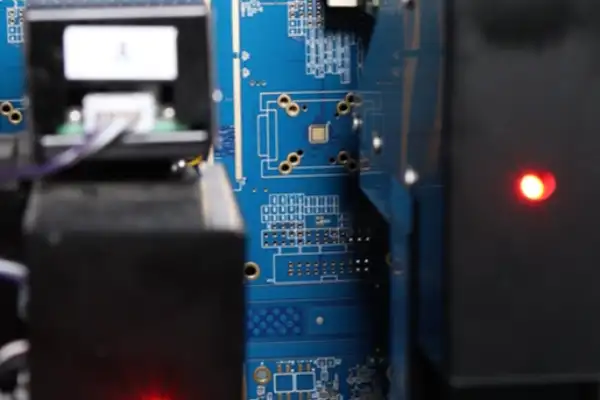
Plenty of HDI PCB manufacturers today advertise how fine their minimum trace width and spacing can go, but for medical lasers, those numbers are actually not the most critical factor. What genuinely affects safety is whether they can guarantee that creepage distance across an isolation gap remains stable after repeated thermal cycles. Once the board is running, the area near the laser routinely exceeds 80°C, and FR4’s CTE causes stress between via copper and pads — over time, micro-cracks can eventually break through the isolation barrier. So over the past few years we have set an ironclad rule: all isolation slots and holes must be plugged and capped with copper, and ground-loop impedance testing has to be spot-checked — not on a sample of a few boards, but on every single board.
On grounding, there is one point I especially want to emphasize: protective ground and signal ground must never be treated as interchangeable. Some designs, for convenience, connect the enclosure ground point directly to the PCB’s analog ground, and the result is that the moment the laser activates, patient leakage current exceeds spec. Our approach afterward was to route protective ground on its own dedicated heavy copper trace to a purpose-built ground terminal, connected directly to the enclosure’s metal post with no via transitions in between. Consider that a 0.1-ohm requirement — if you tried to carry fault current through a single 0.3mm-diameter via, it would blow instantly, so you need a large area of copper along with multiple parallel vias to distribute the current. These details were all worked out through repeated, close collaboration with a reliable HDI PCB supplier.
There is another commonly overlooked issue on a laser device’s PCB — the layout of optocouplers and isolated DC/DC modules. Many people think placing components on either side of the isolation barrier is enough, but the inner-layer copper underneath an optocoupler, if it crosses over the isolation barrier, still introduces parasitic capacitance that lets leakage current creep upward silently. We once got stuck on exactly this item during an IEC 60601-1 test, and only after hollowing out all reference layers underneath the isolation barrier, leaving nothing but insulating material, did that value finally come down to an acceptable level. So now, when I lay out a board, I always draw the isolation barrier first and place components afterward — get the order backward and you end up redoing the work over and over.
Overall, building a Medical Laser Equipment PCB is not a test of how fast you can draw a layout — it is a test of your reverence for every physical detail. A laser can be gentle or it can be violent, and it all comes down to whether the circuit board can shut off that energy obediently before it spirals out of control. Finding an HDI PCB manufacturer who genuinely understands this matters far more than finding a cheap supplier, because every millimeter of creepage distance and every ground connection on that board directly affects the safety of the end user.
Working in medical laser equipment, a lot of people jump straight into obsessing over laser parameters and optical design, treating the circuit board as a simple carrier. But after a few projects, you learn that if something goes wrong with this board, no matter how impressive the rest of the system’s specs are, they mean nothing. I once handled a Q-switched laser for dermatology use, and the ultimate problem was not the light source — it was an outsourced PCB we had assumed was good quality, which developed an inner-layer micro-short under sustained pulsed operation, causing the laser to misfire intermittently. Since then, I select suppliers with extreme caution — especially for boards involving laser driving and interlocks, I insist on a supplier that has actually built medical laser equipment PCBs before, ideally one that continuously supplies similar devices — not the kind of shop that does generic consumer-electronics HDI work.
Laser switching control — many people think it is just a matter of the driver chip giving a signal. But in a medical device, the safety of turning the laser on and off rests entirely on the hardware interlock loop, and there can be no ambiguity in this circuit. My habit now is that everything involved in interlocking — from the emergency stop button, key switch, to the fiber-connection detection microswitch — must run through pure hardware logic, with absolutely no dependence on the MCU judging state before acting. Even if the MCU crashes or the program runs off into the weeds, once an interlock trips, the laser driver enable must be cut microsecond-fast. If the HDI PCB supplier you choose lacks this kind of high-reliability interconnect experience, they might not even properly calculate the copper trace width and via current-carrying capacity from the relay contact to the driver MOSFET — and after aging tests, resistance rises, the voltage drop affects the reference voltage, and laser power drifts.
There is another easily overlooked point — overcurrent protection for the laser diode has to sit at the very front end of the driver circuit, built with a high-speed comparator into a hardware window. I have seen designs that took the easy route, implementing overcurrent protection through the MCU’s ADC interrupt — from sampling to comparison to shutoff, the path was simply too long. If the laser cavity leaks light, or the fiber connector is not properly aligned, a transient reflection can come back, and before software even has a chance to react, the transistor has already burned out. So on my current boards, the comparator output connects directly to the driver MOSFET’s gate, using an active-low, normally-closed logic, so that even if the comparator loses power, it still shuts off. This circuit requires extremely careful routing on a multilayer board — it cannot be allowed to couple with the power loop, which demands that the HDI PCB manufacturer be genuinely proficient in stack-up design and impedance control — an ordinary four-layer board simply will not do.
Interlock loop verification is also a meticulous task in itself — you cannot just check for continuity with a multimeter and call it done. For every interlock point, you have to use an oscilloscope to capture the falling edge of the enable signal, and my experience is that it cannot exceed 10 milliseconds — and you need to capture that dozens of times to catch any occasional delay. Fault injection also has to be done — for instance, simulating relay contact welding, forcibly shorting a particular interlock switch, and checking whether the system actually enters a safe state instead of continuing to fire the laser. If there is a hidden weakness in the board’s own routing during these tests — for instance, if the interlock signal line runs too close to the laser driver pulse line — interference can cause the interlock to misjudge, causing the machine to lock up frequently, giving users a poor experience. So finding a reliable HDI PCB manufacturer who can deeply engage with the design is far more worthwhile than swapping boards after the fact.
There is one thing about building medical laser equipment PCBs that left a particularly deep impression on me. It was not some especially difficult technical spec — it was that you can never predict which stage is going to suddenly stall your project. Last year, one board functioned perfectly, but the moment it hit EMC testing, radiated emission spiked straight up near 300MHz, and nothing we did could bring it down. It felt exactly like locking your front door carefully only to have a burglar come strolling in through the window.
After a post-mortem, we found the problem originated in the high-speed pulse loop of the laser driver section. The instant a high-frequency current surge hits, the entire board effectively turns into an antenna, with noise bouncing off the traces and radiating outward. A lot of people think EMC is something you solve at the very end by adding a shielding can or slapping on some copper tape — but it is nothing like that. The real work has to be embedded right from the PCB layout stage. For instance, I keep the power loop as short as possible, hugging the return path tightly, and sometimes deliberately split the ground plane, then use a bridging capacitor to redirect noise somewhere harmless. Experienced HDI PCB suppliers immediately understand these moves — inexperienced ones just give you a pile of length-matched traces without ever considering what shape the current loop actually takes.
On the subject of suppliers, I have gotten burned too. Medical laser equipment demands extremely high board reliability — it is not enough to simply be capable of assembly. Once, I found a small shop that claimed to be able to do HDI PCB — the laser-drilled vias came out with a hole wall as thin as paper, and it cracked outright after a single thermal cycling test. Since then, I essentially only work with HDI PCB manufacturers who genuinely understand medical-board process — they know where copper thickness needs to be beefed up and where low-loss substrate is needed, none of which is in the spec sheet, yet all of which determines whether a board can survive long-term pulsed stress.
There is also a counterintuitive point. A lot of people assume the faster a protection circuit responds, the better — one-microsecond cutoff sounds impressive. But in actual testing, I have found that too-fast a cutoff can actually excite a high-voltage spike on the cable’s parasitic inductance, damaging other components instead. I now lean toward letting the protection circuit be slightly “softer,” adding a few dozen nanoseconds of filtering delay so the shutdown action is a bit gentler, while building the snubber loop into the front end. Testing this way, component stress actually ends up lower, and performance shows no degradation even after repeated overcurrent testing.
At the end of the day, medical laser PCB work does not come down to some secret trick — it comes down to repeatedly wrestling with every single detail. If a test fails, you go back and revise the board, test again, revise again, until you genuinely trust it. There is no shortcut.
Case Study: Extreme Testing, First-Article Inspection, and the Zero-Tolerance Standard
Working with medical laser equipment PCBs over these past few years, my biggest realization is that the margin for error here is extremely low — you essentially get no chance for a redo, so the moment you choose who builds your board, you have already largely decided whether things will go smoothly downstream.
Many teams treat a Medical Laser Equipment PCB as an ordinary industrial board and hand it to whichever shop quotes the lowest price, only to discover during the EMC stage that copper thickness is uneven, trace spacing control is loose, and even basic impedance consistency cannot be guaranteed. At that point, switching suppliers essentially means re-prototyping from scratch, and the schedule cost simply cannot be absorbed. I now lean toward locking in a genuinely medical-device-savvy HDI PCB supplier from the very start, rather than just checking how many drilling machines they have on the production floor. If you talk to them about creepage distance and partial discharge and they engage with real understanding, that is what matters — otherwise you send over the drawing and they do not even understand why an isolation slot needed to be drawn that way, and everything downstream becomes a landmine.
There is an HDI PCB manufacturer we have partnered with long-term that left a strong impression. When their engineering department gets a Gerber file, the first thing they do is not panelization — they single out the high-voltage regions and cross-check the insulation dielectric thickness against double-safety certification requirements. This habit is worth more than any verbal promise, because in medical lasers, transient stress from pulses that regularly reach several hundred volts is not something you can survive purely on luck.
On power-rail noise, many people habitually pile on components — but I have increasingly come to feel that brute-force capacitor stacking just sets a trap for yourself. This is especially true for the supply line feeding a high-power semiconductor laser, where the current slew rate is extremely high — parallel a row of low-ESR ceramic capacitors without properly calculating the resonance point, and you may actually push noise higher at a certain frequency band instead. I now deliberately reserve a ferrite-bead pad on that trace, without soldering anything on immediately — instead, I first scan the board with a spectrum analyzer to locate the real interference peak frequency, and only then match the appropriate suppression component. Otherwise, so-called “filtering” is just fooling yourself.
There is another step that is easy to skip — routing for optical feedback signals. If differential tight-coupling and shielding copper are not applied here, electromagnetic interference in the environment will couple straight into the closed-loop control path, causing visible low-frequency jitter in output power. This kind of jitter might be completely invisible during bare-board debugging at room temperature, but the moment the board goes into a metal enclosure near a switching power supply transformer, the problem fully surfaces. So my current approach is to reserve at least two stages of RC network at the ADC front end, and I insist on using feedthrough capacitors for the final common-mode stripping stage — the cost is a slightly larger board area, but that is a fully acceptable tradeoff compared to repeatedly reworking the structure after radiated emissions fail at final integration.
On the subject of full-system testing, many people assume that once conducted and radiated emissions pass a standard sweep, everything is settled. In reality, what causes the most headaches is when interlock ports mysteriously glitch during electrical fast transient burst testing. I have hit this twice, and each time it nearly derailed our certification schedule. After that I learned my lesson: every external interface, regardless of signal rate, gets a TVS diode plus a common-mode choke, and the protective ground return is routed separately on its own heavy trace, never sharing the logic ground; on the software side, we absolutely never debounce interlock signals — that is a hard line, because a safety loop must respond in hardware, and any delay could be flagged as non-compliant by a reviewing certification body. You might get lucky in the lab, but at type testing you will get caught every time.
On environmental testing, I believe the most underestimated factor is insulation resistance decay after damp heat exposure — especially on high-density HDI boards using blind and buried vias, where interlayer micro-cracks, once they absorb moisture, will slowly cause leakage current to climb under a several-hundred-volt bias. By the time you discover the withstand-voltage test fails, you often have no choice but to cross-section the board for analysis, and by then it is already too late. So now, with every batch of boards, I pull a few samples and run three thermal-shock cycles before running the full double-85 test — strictly speaking this is not part of the standard process, but it has genuinely helped us screen out two batches with hidden delamination in advance, saving the huge waste of discovering problems only after full assembly. The money and time spent earning these lessons stick with you far more firmly than anything in a textbook.
Documentation, Traceability, and Why Certification Success Starts at Supplier Selection
When I first got into medical device development years ago, my understanding of PCBs was still stuck at the level of “as long as the traces connect, it works.” Reality later taught me a harsh lesson, especially in medical lasers, where I discovered that a reliable board practically determines whether the entire device lives or dies. At the time, we had a low-power dermatology laser project — the prototype ran perfectly in the lab, but the moment it reached a customer site, all kinds of strange problems appeared: laser output would occasionally jump, and the power curve looked like an EKG readout. It took two full weeks of investigation to trace the problem back to the main control board — not a design flaw, but insufficient interlayer withstand voltage in the board itself, combined with micro-cracking in the HDI vias after repeated thermal cycling, causing intermittent signal paths. From that point on, I started seriously researching how a Medical Laser Equipment PCB should really be selected.
Many people assume a laser device is just power supply, light source, and cooling system stacked together, and that the PCB just needs to carry current — that thinking is far too naive. A laser pulse’s rising edge routinely demands nanosecond-level speed, meaning parasitic inductance in the driver loop has to be pushed extremely low — a few millimeters of extra trace length is enough to cause overshoot or even ringing, directly affecting laser output stability. An ordinary through-hole board simply cannot handle this; you are forced toward HDI. The HDI PCB manufacturer I later found showed me cross-sections of laser-drilled micro-vias — hole diameters as small as 0.1mm, with pads stacked directly on blind vias, immediately raising routing density and letting the path between driver chip and laser diode shrink to a minimum. The benefits of this compact layout go far beyond the obvious ones — beyond smaller size, electromagnetic interference drops significantly, which matters enormously when a pile of equipment is running simultaneously in an operating room.
Selecting a good HDI PCB supplier is even more agonizing than choosing the design scheme. Plenty of shops on the market can do HDI, but very few are willing to accommodate the small-batch, multi-round validation that medical devices require. I remember vividly — we contacted five suppliers at the time, and three of them backed off the moment we mentioned we needed 100% flying-probe testing plus impedance coupon testing and 288-degree thermal-stress sampling. The one we ultimately partnered with laid everything out openly for us — inner-core substrate material selection, number of lamination cycles, plating-fill copper uniformity — and even proactively suggested using a modified polyimide substrate to handle the high temperatures generated by long-duration laser operation. What I learned from this is: do not just look at a supplier’s advertised layer count and minimum trace width — check whether they perform medical-grade reliability validation, and whether they have withstand-voltage and CAF-resistance test data. That is the real hard metric directly tied to a Medical Laser Equipment PCB.
The laser device itself is genuinely delicate. Even a slight temperature fluctuation at the diode’s facet causes wavelength drift and efficiency loss. If the PCB’s thermal management is weak, even the most expensive TEC temperature controller becomes useless. I once saw a counterexample from a peer’s Q-switched laser — the power module’s pad used only a single layer of 1oz copper, heat could not escape, and after firing repeatedly the junction temperature exceeded limits, burning out the pump source outright. On our own redesign, we mandated 3oz thick copper for power traces, and split the inner ground plane into multiple sections, filling them with thermal adhesive down to the metal base. If the HDI PCB manufacturer lacks sufficient experience with these kinds of details, they can easily compromise on process — for instance, getting the etching compensation wrong for heavy copper combined with fine-pitch traces — and yield can become unbearable. So at the end of the day, a PCB is not just an electrical connection — it is itself part of the thermal path and part of the structural reinforcement, especially for laser systems fitted with a water-cooled plate, where the PCB’s warpage and Z-axis expansion coefficient directly affect whether the sealing gasket will slowly leak.
Looking back now, a good Medical Laser Equipment PCB is the “skeleton” of the entire laser device. It silently bears current, heat, and vibration, all while guaranteeing signal cleanliness. I would rather spend an extra few weeks upfront hammering out process boundaries with an HDI PCB supplier than get chased by field failures at a customer site later on.
Building hardware for medical laser equipment over the years, my deepest realization is that everyone’s attention gets fixated on the certification testing itself, while forgetting the most exhausting part behind the scenes — documentation. If you have never been through it, you can never imagine just how much of the time spent getting a Medical Laser Equipment PCB from design to certified approval goes into paperwork — potentially more than the time spent debugging the actual circuit. An FDA or CE-MDR reviewer will never stand in your lab watching your oscilloscope — they only trust the stack of documents you submit. So many times, I would rather spend extra time finding an HDI PCB manufacturer able to deliver a complete set of process documentation, than cut costs and gamble on a supplier’s willingness to cooperate.
The biggest difference between a Medical Laser Equipment PCB and an ordinary industrial board lies right here. Parameters like laser pulse width and peak power ultimately have to be guaranteed by the board’s trace impedance and copper-thickness uniformity — and what a certification body wants is not your verbal assurance, but real test reports and design calculation documents. I once saw a team whose board performance fully met spec, but the project was delayed over four months purely because the HDI PCB supplier could not provide a cross-section report for laser blind-via copper fill. This type of board is typically high-density interconnect, and blind-via processing quality directly relates to signal integrity — without those few cross-section photos in the documentation, you can cut the physical part open in front of the reviewer and it still would not help.
Nowadays, when I approach an HDI PCB supplier, I ask upfront: can you provide a full-process traceability record that meets medical-device documentation requirements? Not the simple certificate of conformity type — I mean, from inner-layer imaging through to final surface finish, every single process step’s parameters, inspection data, even the operator ID, all need to be traceable and correlated. In the CE technical file, you are required to identify the PCB’s critical components — isolation transformers, safety capacitors, for example — and the specification sheets and certification documents for those components must strictly correspond to the reference designators listed in the PCB design files; get one number wrong and the entire traceability chain breaks. I once got sent back for corrective action by a notified body purely because an optocoupler’s UL certificate version number was not updated — that feeling was genuinely one of the most frustrating experiences I have had.
Domestic NMPA registration is the same story. A lot of people think as long as you follow GB 9706 and GB 7247 for testing, that is sufficient — in reality, the prerequisite for a smooth test is that the design documentation is already fully closed-loop. My habit is to lay out the insulation diagram, creepage distance calculation table, and critical component list right at the schematic stage, updating the risk analysis report as I go through PCB layout. This may look slower, but you eventually find that every test item in the design verification report can directly cite the documentation you accumulated earlier, with no need to circle back and patch holes. I have lived through that scramble of cobbling together documentation at the last minute once, and I never want to go through it again.
At the end of the day, compliance for a Medical Laser Equipment PCB is not something you can knock out with a one- or two-month sprint at the end. It requires choosing the right partner from the very beginning — an HDI PCB manufacturer whose process capability and documentation capability must both be equally strong. I will even tell a supplier directly that what I need from them is not just the board — I need a complete manufacturing-process documentation package that can be seamlessly embedded into my technical file. This mindset might seem overly rigorous, but for medical laser equipment, rigor genuinely is the shortest path.
Case Study: When Cost-Cutting on the Interlock Isolation Groove Bit Back
Not long ago I was chatting with an engineer who builds laser aesthetics equipment, and he mentioned a product that occasionally reported interlock faults at customer sites, but every time it was pulled apart and checked, everything looked normal. This dragged on for several weeks before they finally traced the problem to the PCB itself. That board used a conventional lamination structure, and the interlock signal trace ran too close to the pulse driver circuit — under humid weather, once the board absorbed moisture, its dielectric constant shifted, doubling crosstalk, and the hardware comparator started false-triggering. This reminded me of a similar case I handled a long time ago, also involving a Medical Laser Equipment PCB — the interlock circuit had already been designed with dual-channel redundancy, but false triggering still occurred after actual assembly. When we pulled it apart to investigate, we found the board shop had, during manufacturing, mixed the ground return of one channel’s signal together with the power ground — effectively rendering the redundancy completely void.
These two incidents made me become especially cautious about selecting an HDI PCB supplier. Circuitry in medical laser equipment, especially safety-related paths like interlocks, is fundamentally not something you can just hand off to a factory as a schematic and expect it to work out. Many HDI PCB manufacturers have strong laser micro-drilling capability, can hit trace width and spacing of two mils, and deliver fast turnaround — but their understanding of medical-device safety design logic is essentially zero. One time I had a new supplier prototype a board — in the Gerber file, I had specifically left extra creepage distance for reinforced insulation next to the interlock relay coil, and their engineering team, in the name of “optimizing” the layout, removed that slot entirely, even believing they had helped me save space, completely unaware that at 240V working voltage that distance was nowhere near sufficient.
So now, when I evaluate an HDI PCB supplier, I do not particularly care how many laser drilling machines they have on the floor — I go straight to whether they have built cases involving medical laser drivers before, especially whether they have handled real-world problems like interlock redundancy circuits and isolation of weak photoelectric feedback signals. A genuinely reliable manufacturer, once they receive your stack-up plan, will turn the question back on you: does this inner-layer differential signal need to be controlled to 100 ohms impedance? Can that opening under the optocoupler be changed to a hollowed-out copper area instead, guaranteeing creepage distance without affecting board thickness? These details are questions a factory without relevant case experience simply cannot ask.
At the circuit level, I now lean toward designing interlocks with a “hardware-first, software-only-for-logging” model. For instance, we use dual-channel comparators paired with an independent relay cutoff path, with each comparator’s reference voltage generated by its own separate zener diode — so even if one drifts, the other can still back it up. Software is only responsible for reading state and latching fault codes, never participating in any decision logic. This kind of design, during PCB layout, requires the power and ground for the two comparator channels to be completely separated, with generous trace spacing between them, and they cannot share a single via — which places extremely high demands on the HDI PCB manufacturer’s process consistency. Any single trace made too fine or copper thickness left uneven can shift the interlock’s failure threshold — a risk that is absolutely unacceptable in medical equipment.
Back when I first entered this field, medical laser equipment PCB design and ordinary industrial board design were simply not on the same path at all. Many people think all you need is to get the laser driver circuit working and light coming out, only to discover during the submission process that the problems all trace back to the board itself. Medical laser equipment PCBs, especially ones carrying high-voltage pulses with instantaneous current surging to several dozen amps, will likely fail to meet even the most basic creepage-distance requirement if built by an ordinary HDI PCB shop. The most absurd case I ever saw was a four-layer board that, because copper thickness was insufficient combined with an inner-layer isolation gap designed too small, was punctured outright during CE certification’s transient surge test — a scorched trail ran from the high-voltage end all the way to the signal region, and the entire board was scrapped.
We later switched to an HDI PCB manufacturer specializing in medical-device boards. Honestly, their process capability was nothing extraordinary, but their strength was in genuinely understanding the domain. The kind of mixed design common in laser equipment, requiring wide traces for large current alongside fine traces for analog sampling in the same footprint, is something many HDI PCB suppliers simply cannot handle. They would either recommend thickened copper foil at the expense of trace-width control, or tell you outright that stacked laser-via structures cannot be done. In the end, we compromised — adding extra isolation slots and islands on the board, re-adjusting the ground-plane partitioning between the high-voltage and low-voltage regions, and finally getting withstand voltage and leakage distance up to standard. This experience made it completely clear to me that having a fully certified factory does not guarantee peace of mind — you have to personally oversee their inner-layer process and lamination structure, especially given how a medical laser’s pulsed energy delivery ages the dielectric material under repeated thermal shock — ordinary FR-4 simply cannot hold up.
On certification, domestic NMPA and FDA emphasize very different things. FDA cares more about the safety interlock behavior under failure modes, essentially wanting every protection loop implemented independently of the MCU, purely through hardware logic. Domestic testing institutes, meanwhile, scrutinize a PCB’s flame-retardant rating and CTI value in far more detail — sometimes when you try to apply IEC 60601’s general requirements, they will additionally require you to provide reflectivity data for the board material under exposure to a specific laser wavelength, to prevent accidental scattering from causing secondary risk. Many HDI PCB manufacturers simply cannot grasp this point — they think as long as the traces connect correctly and impedance control is on target, the job is done, without any consideration for whether the laser’s optical path might strike the board. My current habit is to overlay the laser optical path simulation with the PCB’s 3D model right at the project-initiation stage, proactively avoiding any copper foil region that could possibly be struck directly — even scattered light, accumulated over the long term, can degrade the solder mask layer and eventually create a leakage path.
When choosing an HDI PCB supplier, I do not just look at whether they hold ISO 13485 — that certification alone is too shallow a signal. I ask directly how many medical laser equipment boards they have handled, and whether they can produce concrete withstand-voltage test reports and partial discharge test data. Plenty of small shops, the moment they hear the word “laser,” immediately promise they can do it, but cannot even explain how the ringing and overshoot common in laser driver circuits affect the long-term reliability of the PCB’s insulation layer. I got burned by this before, so now I would rather pay a bit more to find HDI PCB manufacturers who have supplied boards for large-scale imaging or radiotherapy equipment — at least they understand how demanding documentation traceability is for medical boards. Every lamination cycle and every drilling parameter change requires a complete record — otherwise, when a device fails in the field and you have to trace the issue back upstream, you have no evidence to offer, and an FDA warning letter can show up at any time.
At the end of the day, a Medical Laser Equipment PCB is not simply an electrical connection component — it is a carrier bearing the dual responsibility of safety isolation and energy transmission. Every trace, every isolation slot, every laser-drilled hole on that board directly affects the safety of doctors and patients. Do not expect software to compensate for a hardware design flaw — that is self-deception. My approach now is to design every safety-critical loop with redundancy right from the schematic stage, leave more than double the required creepage distance in the PCB layout, and have at least two HDI PCB suppliers prototype in parallel for comparison testing — one following the standard process flow, the other dedicated to extreme stress testing, like operating under high-temperature, high-humidity, powered conditions and rapid thermal cycling, to see which weak point fails first. Only by doing this can you expose potential certification risk during the design stage, rather than waiting until the entire product is finished before scrambling to rework the board at the last minute.
Do you think a rain sensor is just a simple circuit board?
Sunroof control PCB design is easy to get wrong when teams are
As a veteran hardware engineer, I’ve found that a lot of people
- Pienten ja keskisuurten erien tuotannon asiantuntija
- Korkean tarkkuuden piirilevyjen valmistus ja automatisoitu kokoonpano
- Luotettava kumppani OEM/ODM elektroniikkaprojekteihin
Aukioloajat: (ma-la) klo 9:00-18:30.
Get quote, solution or any question, Andre always here to help