

Circuit Board Prototyping Choices That Actually Matter for an Automotive LiDAR PCB
In circuit board design, prototyping is often the most creative and most
I’ve seen too many teams stumble in circuit-board development. They always assume that building a polished prototype is the end of it — in reality, that’s just the first step of a very long journey.
I remember a team that spent three months polishing a flawless Prototype PCB Production sample. Every functional test passed, and everyone thought victory was in sight. Then, on the very first day of mass production, trouble hit — the printing machine simply couldn’t scrape the solder paste evenly. It later turned out there was a problem with the stencil-aperture design. That so-called generic stencil barely worked at the prototype stage, but the moment it hit a high-speed production line, even a few-micron difference in solder-paste thickness scrapped the entire batch.
That incident made me realize the lab and the factory are fundamentally two different worlds. In the lab, you can slowly fine-tune every parameter; a factory production line gives you no second chances. Sometimes it’s that tiny aperture angle on the stencil that decides an entire project’s fate.
Another common misconception is assuming the more refined a prototype, the better. Actually, over-polishing can mask real problems. I’ve seen someone build a prototype even more refined than the mass-production version, only to have every process issue that should have surfaced get hidden under that perfectionism — by the time real volume production started, they couldn’t even meet basic soldering yield.
What’s the genuinely smart approach? When doing Prototype PCB Production, simulate the mass-production environment — even if it costs a bit more upfront, use the same stencil specification you’ll use later. That way, you catch problems in time and adjust, instead of discovering a design flaw only after investing hundreds of thousands into tooling.
A team we recently worked with did this well. At the sampling stage, they directly adopted the mass-production stencil standard. It cost 20% more upfront, but it saved three months of debugging time down the line. Their product yield is now 15% higher than their peers — was that money well spent? Absolutely.
At the end of the day, what circuit-board development fears most is self-deception — mistaking lab success for a smooth factory rollout. Details overlooked at the prototype stage often become the most fatal hidden reef once mass production begins.
After years in hardware development, I’ve picked up one insight — a lot of people oversimplify prototyping. They think it’s a success as long as the circuit board lights up and performs its basic function. In reality, that’s still a long way from a genuine product.
I remember a smart-home project last year. Rushing to meet a deadline, the team hand-soldered a few boards directly in the lab, and every functional test passed — everyone was pretty pleased. Then, once we moved to mass production, the problem surfaced: X-ray inspection on the production line revealed a large number of voids underneath the BGA chip — the kind of thing that’s simply impossible to catch at the prototype stage.
This incident made me realize that prototyping can’t just focus on immediate functional validation — you need to factor in mass-production inspection standards ahead of time. For example, now we insist on introducing X-ray sampling right at the prototype stage, especially for components like BGA where solder joints are invisible. It does add some cost, but it’s still far better than scrapping an entire batch during volume production.
Another easily overlooked point is component supply chain. Once, we chose a niche chip for a prototype — its performance was genuinely outstanding and the price was reasonable. By the time we were ready for mass production, we found the supplier’s lead time stretched to six months, nearly stalling the entire project. So now I’ve made it a habit to simultaneously evaluate the supply stability of key components while prototyping — I’d rather accept slightly lower performance than choose a mainstream, widely available part number.
A genuinely reliable prototype should be a board that can withstand scrutiny under a magnifying glass. It shouldn’t just work fine in the lab — it needs to fit a factory’s production rhythm. Those seemingly redundant inspection steps often save you at a critical moment.
A recent industrial-controller project we’re working on has followed mass-production standards from day one of prototyping, even moving environmental testing forward. Progress is a bit slower, but it feels far more solid. After all, what hardware development fears most is carrying a hidden risk into the mass-production stage — the cost of fixing it there is far too high.
Every time I see an engineer excitedly debugging a freshly made circuit board’s function, I want to remind them not to pop the champagne too early — that shiny board in your hands might just be a greenhouse flower, unable to withstand the storms of the real world. I’ve seen too many projects fail at exactly this hurdle between lab and factory.
When doing Prototype PCB Production, a lot of people easily fall into a misconception, assuming that as long as the board lights up and basic function runs, everything’s settled. Actually, that’s exactly the most dangerous moment, because the testing environment at the prototype stage tends to be far too idealized. A factory’s production process is nowhere near as gentle as a lab — a fluctuation in soldering temperature, a slight component variance, even a shift in shop-floor humidity, can all cause an entire batch of products to fail.
Take a case we ran into last year, for example. A team designed a smart-home controller, and every function worked perfectly at the prototype stage, even passing stress testing. But once it hit the mass-production line, trouble started — some boards would develop signal drift after running for a few hours in a high-temperature environment. It later turned out a filter capacitor’s temperature rating was chosen right at the margin — it performed fine in the lab’s air-conditioned environment, but simply couldn’t hold up in real-world usage scenarios. This kind of problem is hard to catch during prototype testing, because you’d never think to simulate the forty-degree temperature on a user’s summer balcony.
PCB manufacturability is genuinely something that needs to be considered upfront. I’ve seen quite a few designs, chasing performance, route traces extremely densely — something you might get away with through manual adjustment at the prototype stage, but the moment it goes to an automated pick-and-place machine, even a slight deviation causes widespread short circuits or cold joints. Rework at that point is far too costly. So now I’ve made it a habit to factor in the production line’s process capability right at the first design version — for example, whether the minimum trace width can meet mass-production requirements, or whether component placement will cause difficulty for assembly.
On testing, I think what’s most easily overlooked is performance under extreme conditions. Many teams only run standard operating-condition tests during prototype validation — that’s nowhere near enough. A real product has to face all kinds of unexpected situations — sudden voltage fluctuation, rapid temperature change, even improper operation — all of which should be factored in early. I remember once, working on a design for an automotive device, we deliberately left the prototype baking in a car under the sun for an entire day, and sure enough, we found stability issues with a few chips at high temperature. If that problem hadn’t surfaced until after mass production, the loss would have been significant.
Actually, what hardware development fears most is assuming that if there’s no problem in the lab, there won’t be one in real-world application either. The road from drawing to product is far more winding than most people imagine. Every time I see a team taking reliability verification seriously right at the prototype stage, I admire them — that’s what genuine professionalism looks like. After all, good design isn’t just about working on paper — it needs to work reliably in the user’s hands.
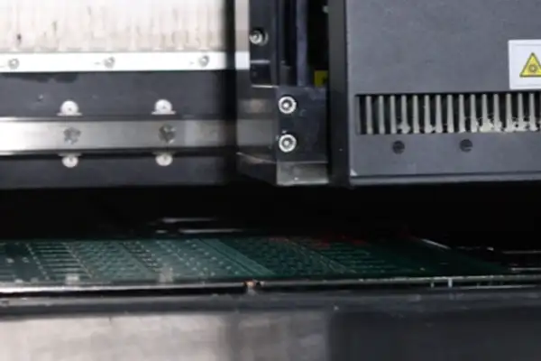
I’ve seen too many teams stumble in circuit-board development. They always assume building a polished Prototype PCB Production sample is the end of it. In reality, that’s just the warm-up. What genuinely tests you is the downstream mass-production stage. The gap between the two is enormous.
I remember a smart-home team who came to me for consultation last year. They showed me a carefully tuned sample board — the functionality was genuinely impressive. But when I asked how they planned to handle a ten-thousand-unit order, they suddenly froze. That’s the classic problem — treating the prototype as the finish line.
The transition from prototype to mass production genuinely tests a team’s foresight. You need to think ahead about process stability. Something as seemingly simple as soldering temperature might not be a problem at small batch, but scale it up to thousands of units and it becomes a disaster. I’ve seen cases where an entire batch had to be reworked due to solder-paste batch variation.
Many engineers today rely too heavily on a contract manufacturer’s default settings. That’s genuinely dangerous. Every product has unique process requirements. You need to personally stand on the shop floor watching workers adjust equipment parameters. Sometimes spending an extra half hour fine-tuning conveyor-belt speed can avoid a loss of thousands of units down the line.
What I most want to remind people is not to oversimplify the testing process. Poking around waveforms with an oscilloscope in the lab is one thing; running twenty boards a minute on a production line is an entirely different matter. You need to design an inspection plan that’s both rigorous and efficient — that balance is genuinely hard to strike.
Actually, finding a manufacturing partner is like finding a spouse. You can’t just look at whether they can produce a beautiful sample — you also need to assess whether they have the willingness and ability for continuous improvement. A good factory proactively discusses process details with you, rather than mechanically producing to the drawing.
A genuinely reliable product manager considers mass-production feasibility right at the sampling stage — for example, deliberately designing component spacing looser than conventional requirements, leaving fault tolerance for the production line. This seemingly conservative approach often does the most to guarantee delivery quality.
At the end of the day, hardware-product reliability isn’t built up by luck — it’s achieved through careful design at every single stage. From the very first sample board, you need to hold yourself to mass-production standards — that’s the only way a good idea genuinely becomes a trustworthy product.
I’ve recently noticed a genuinely interesting phenomenon — a lot of people, when doing Prototype PCB Production, always want to rush the sample out, overlooking that this is actually a critical step in preparing for mass production. I only came to understand this after taking plenty of detours myself.
I remember once, rushing to get samples out for functional testing, we casually picked a cheap solder-paste model, only to discover during small-batch trial production that the soldering-defect rate was especially high. We later had to re-validate the material, delaying the schedule by a full month. That incident taught me that from the very first sample board, you should use the same process parameters as final mass production. Initial cost might be a bit higher, but it avoids a much bigger loss later.
Now, when I do prototype validation, I always set stencil-aperture design and reflow-temperature curves according to mass-production standards. Some people think that’s overly meticulous, but I’ve found that as long as you build a solid foundation upfront, subsequent scale-up goes far more smoothly. This is especially noticeable when a product needs to reach market quickly — the return on that upfront investment is especially clear.
Once, our team found a particular component’s soldering kept having problems during trial production. Tracing it back, we found the placement-machine precision used at the prototype stage didn’t match the mass-production equipment. Even though the sample functioned normally, a tiny discrepancy got amplified into a fatal problem during volume production. That lesson gave me a habit of recording detailed process parameters at every single sampling run.
Actually, what electronics manufacturing fears most is assuming things without verifying. A lot of people think a sample just needs to power on — forgetting that these details snowball to affect the entire production flow. I now pay especially close attention to material-source stability — even for just ten sample boards, I insist on using components from a legitimate channel.
A recent project has us simulating mass-production storage conditions right from the first batch of samples. It turned out we genuinely found that a certain surface-finish method accelerates aging under specific temperature and humidity conditions. If we hadn’t validated this ahead of time, the problem might not have surfaced until it reached the customer.
I think what makes hardware work genuinely interesting is that every stage is interlinked. Sometimes the time spent on upfront verification looks redundant, but it helps you avoid a lot of pitfalls later. Especially as a product prepares to enter large-scale production, those seemingly trivial details become absolutely critical.
New engineers on my team often ask why I hold sample boards to such strict standards. My answer is always the same: a good start is half the battle — and in electronics manufacturing, that’s more true than anywhere else.
After years in circuit design, I’ve picked up a bit of know-how — a lot of people think building a polished prototype is the finish line. Actually, going from lab to production line is where the real test begins. I remember once our team spent two months finalizing Prototype PCB Production, and the test results were genuinely ideal — but the moment we hit mass production, we stumbled badly.
Where was the problem? It wasn’t a design issue, and it wasn’t a process issue — it was that we relied too heavily on component samples from a single supplier. At the time, rushing to meet the deadline, we grabbed a few sample units directly from a partner to test performance — flawless. But once we placed a formal order, we found that particular batch of chips simply wasn’t available in stock. The supplier casually said, “That was leftover inventory from last year’s production — it’s been discontinued.” That nearly stalled our entire project.
That reminds me of another, even more hidden pitfall — PCB board-material stability. Once, the copper-clad laminate we used performed excellently in lab conditions, but during mass production, we hit the rainy season, warehouse humidity exceeded spec, and a batch of boards developed micro-cracks in the pads. This kind of problem is simply impossible to catch at the prototyping stage, because samples are made in small batches and used immediately. But during large-scale production, board material sitting in a warehouse for two weeks can absorb moisture and deform.
Now I place a lot of weight on component supply-chain transparency. For example, some chips claim identical parameters, but the actual temperature performance from different factories can differ by more than ten degrees. We once used a power-management chip that hit 95% efficiency during small-batch trial production, and after scaling up with a different contract manufacturer, efficiency dropped straight to 88%. It later turned out the first batch of samples were special OEM-spec units, not even the same tier as the commercially available version — the kind of gap that matters enormously on a Bidirectional DC-DC Converter PCB, where efficiency and thermal margin are everything.
Even more headache-inducing is component aging. Freshly unpackaged capacitors and resistors in the lab are of course stable, but material on a production line might have been sitting in a distributor’s warehouse for half a year already. Once, running a high-temperature test, newly arrived surface-mount capacitors collectively burst during reflow soldering. We later found the storage-environment temperature had exceeded spec, causing the dielectric material to age prematurely.
So now I’ve made it a habit — every new project, I deliberately test some “edge conditions.” For example, mixing PCBs from different batches, deliberately assembling with near-expiry components, even simulating transportation vibration. These seemingly troublesome practices have actually helped us dodge quite a few landmines.
A genuinely reliable product can’t just shine under ideal conditions — it needs to withstand every kind of real-world manufacturing stress.
I’ve seen too many teams stumble at the hurdle between sample and mass production. Holding a few flawlessly functioning sample boards, they excitedly get ready for production, only to have problems come one after another. This actually isn’t the factory’s fault — it’s a gap in our understanding of product development.
While building a sample, we tend to focus only on whether the circuit runs and whether the signal is normal. Hand-soldering and debugging in the lab can, of course, solve most problems. But once you actually enter a production line, the situation is entirely different. Factors like automated pick-and-place-machine precision and reflow-soldering temperature curves are rarely seriously considered at the sample stage.
I remember once designing a high-frequency board whose sample performance was genuinely outstanding. But once it hit the production line, we found yield simply couldn’t climb. It later turned out the pad design sat too close to the board edge, and the pick-and-place machine’s nozzle kept knocking components slightly off. This kind of detail simply never surfaces during hand soldering, but on a high-speed line, it becomes a fatal flaw.
Another commonly overlooked factor is material consistency. When doing Prototype PCB Production, we might source components from different channels, as long as the parameters are roughly similar. But once in mass production, subtle differences between component batches get amplified, directly affecting the stability of the entire batch.
The genuinely reliable approach is thinking about downstream production from the moment you start drawing the board. For example, making test points large enough for easy contact with an in-circuit tester, and grouping similar-package components together to reduce line-changeover frequency. These seemingly simple adjustments make mass production go far more smoothly.
I’ve now made a habit of asking myself one extra question before every sampling run: can this design accommodate automated production? It takes a bit more time, but it’s far more worthwhile than the loss of a stalled production line later.
At the end of the day, going from prototype to mass production isn’t simply a matter of scaling up — it’s a complete shift in mindset. Only by baking manufacturing feasibility into the design DNA can a good idea genuinely become a reliable product.
I’ve seen too many teams stumble in circuit-board development. They always treat prototyping as an isolated step, as if passing functional testing settles everything. Actually, from the very first board, you need to factor in downstream large-scale production.
I remember a team building a smart-home controller — the Prototype PCB Production stage went smoothly, and manually adjusting a few resistor values solved a signal-interference issue. Then, moving into mass production, they were stunned — a production line can’t manually adjust a resistor for every single board, and the entire batch ended up scrapped. This is the classic mindset of treating the prototype as the finish line.
What genuinely matters is building data awareness right at the sampling stage. For example, on a recent sensor project of ours, we started recording process-parameter fluctuations for every step starting from the first batch of samples. Even though the initial Cpk value was only around 0.8, through more than twenty rounds of small-batch trial production, we gradually pushed process stability above 1.5. By the time formal mass production began, production-line workers only needed to follow the standard process.
Many people think collecting this kind of data is a waste of time, but when a batch-wide problem hits and you’re scrambling to find the root cause, that’s when real delay happens. Once, helping a client analyze a batch of failed boards, we found the cause was uneven immersion-gold thickness. Fortunately, they’d kept thickness records for every batch since the prototype stage, and we quickly pinpointed the problem process step. Without that data, we might have had to shut down the entire production line to investigate.
Now, the thing I emphasize most with my team is: don’t treat mass-production prep as a second project. From the moment you draw the very first version of the circuit, think ahead about how the machine will place components and how the test fixture will be designed. On a recent Bluetooth-module project, we deliberately made three different pad sizes during Prototype PCB Production, specifically to see which one best suited the automated pick-and-place machine’s precision requirement.
This kind of mindset shift takes time, but it genuinely saves a lot of trouble down the line. After all, reworking during the mass-production stage costs far more than fixing something at the sampling stage.
I’ve seen too many teams fall into a trap during the Prototype PCB Production stage. The prototype boards they spend a fortune building look flawless — every function tests fine. Then problems hit the moment mass production begins.
This has to be traced back to the root cause. A lot of people think hand soldering is a safety net — “if it doesn’t work, we can fix it manually.” In reality, that’s exactly what plants the hidden risk.
I remember a smart-home team who came to me for consultation. They proudly showed me ten prototype boards that had all passed testing perfectly — each one hand-soldered and tuned by an engineer. The result: the first mass-production batch of three thousand units had a 15% return rate. Opening them up, they were riddled with cold and dry solder joints.
The problem was exactly in that hand-soldering step. An engineer holding a soldering iron, repeatedly adjusting angle and temperature, can always find a way to make the solder joint work — even if the PCB’s pad surface treatment has a problem, skill can compensate for it.
But a reflow oven on a production line isn’t nearly that flexible.
The real lesson is this: what matters most in Prototype PCB Production isn’t verifying whether the circuit design is correct — it’s verifying whether the manufacturing process can be reliably replicated.
My advice to teams now is simple — build your prototype simulating mass-production conditions.
For example, on a recent medical-device project, we used small SMT equipment for placement right from the first prototype version. It cost a bit more, but it exposed a BGA-package solderability issue early, letting us adjust the PCB surface-finish process in time.
Hand soldering can be a debugging tool, but it can’t be an acceptance standard.
After all, a product is ultimately headed for a production line — not staying in the lab as a display piece.
I’ve recently noticed a genuinely interesting phenomenon — a lot of people, when doing Prototype PCB Production, easily fall into a parameter-chasing trap. They always fixate on extreme values.
I remember a client bringing me a design draft asking whether we could achieve a 3-mil trace width. I couldn’t help but smile — that number does look impressive.
In reality, the minimum trace width a factory advertises is often measured under ideal lab conditions. Once you actually hit the production line, it’s a different story.
I’ve seen too many people pour their energy into chasing extreme parameters.
Pad design is a textbook example.
Once, we received a board.
Actually, what building a sample fears most is exactly this kind of lab mindset. Some people always think pushing trace width to the extreme makes a design look professional.
I’d instead recommend appropriately relaxing requirements at the initial sampling stage.
A lot of people today like to compare prices online.
The genuinely reliable approach is building a solid foundation first.
At the end of the day, the essence of Prototype PCB Production is validating a design concept.
Circuit-board work is genuinely interesting. I’ve seen quite a few teams pour real effort into polishing detail during the Prototype PCB Production stage — repeatedly adjusting the reflow curve until every solder joint gleams — only to find, once they reach mass production, that the whole approach simply doesn’t hold up.
A common misconception is treating the prototype as the final product to be sculpted. In reality, a prototype’s purpose is more like a trial-and-error tool — what you need to verify with it is whether the design concept works and basic function holds up. I’ve seen someone spend two weeks tuning a perfect temperature curve for a lab test board, only to find during mass production that the production line’s reflow oven used an entirely different hot-air circulation method.
Going from prototype to mass production was never simply a matter of scaling up. There’s a subtle turning point here: the lab lets you repeatedly adjust parameters chasing the extreme effect; a production line needs a stable, repeatable process window. You can’t expect every mass-produced board to enjoy the hand-tuned temperature curve of a prototype — that’s neither realistic nor economical.
Material selection also reveals this difference. At the prototype stage, you might casually use whatever solder paste happens to be in lab inventory, but once you genuinely enter mass production, you need to consider whether the supplier can reliably supply long-term, and whether batch-to-batch variation is controllable.
Even more critical is the shift in testing coverage. In the lab, you can inspect solder joints one by one under a magnifying glass; a production line needs an automated solution that can judge an entire board’s pass/fail status within three seconds. This shift in inspection thinking often tests a team more than any technology upgrade.
A genuinely mature engineering team factors in future mass-production possibilities right at the sampling stage. For example, deliberately placing thermocouples at different positions to simulate temperature-distribution variation during large-scale production, or testing three different brands of solder paste in advance to establish a process window.
At the end of the day, going from prototype to mass production requires a restructuring of mindset — the former pursues validating possibility, the latter pursues controlling stability. Teams able to bridge that gap are usually the ones who know how to optimize the right amount at the right stage.
In circuit board design, prototyping is often the most creative and most
A tire pressure sensor that lost signal after six months, taken apart,
A decade in solar taught me that most MPPT controller PCB failures
- Experto en producción de lotes pequeños y medianos
- Fabricación de placas de circuito impreso de alta precisión y montaje automatizado
- Socio fiable para proyectos electrónicos OEM/ODM
Horario comercial: (de lunes a sábado) De 9:00 a 18:30
Get quote, solution or any question, Andre always here to help