
Heat Dissipation Challenges and Solutions in PCB Circuit Board Design
Circuit boards are more than just that green board in a phone
While organizing workshop equipment, I noticed an interesting phenomenon: the most stable PLC controllers, when disassembled, had noticeably different PCB layouts and materials. It’s not simply a matter of using more expensive materials to solve the problem.
Once, I helped someone upgrade the PLC system on an old production line. The original board was prone to malfunctions in the summer. It was later discovered that the problem stemmed from the decreased insulation performance of ordinary PCB materials in high humidity environments. Replacing it with a substrate of a higher CTI rating resolved the issue.
Many people believe that industrial equipment only needs to function properly. However, the PCB design inside a PLC directly impacts the reliability of the entire system.
For example, if the power supply traces are too thin or the copper plating is insufficient, it will easily overheat during long-term operation.
I’ve seen many manufacturers compromise on PCB material to save costs, resulting in equipment malfunctioning within a few years.
Truly reliable PLC designs consider changes in the actual working environment.
Once, testing PLC modules from different manufacturers revealed that the insulation resistance of ordinary boards decreased significantly under high temperatures, while boards with specially selected materials maintained stable performance.
This made me realize that industrial-grade products cannot be judged solely by surface parameters.
A good PCB design is like putting a suitable protective suit on the PLC; it shouldn’t be too thick, affecting flexibility, nor too thin, unable to withstand external interference.
Sometimes, simply increasing the copper plating area or choosing a substrate with a suitable CTI value can significantly improve anti-interference capabilities.
These details often determine whether the equipment can operate stably for a long time.
I believe a reliable indicator of an industrial control board’s reliability is how it handles scenarios where high current and low signal signals coexist. Boards that haphazardly pile power and signal lines together, no matter how cheap, shouldn’t be used in critical equipment.
Truly well-designed boards use a reasonable layering layout and material selection to ensure different circuits function properly and without interference.
This is what industrial-grade products should look like.
I’ve seen too many engineers overcomplicate PLC anti-interference design. The key to equipment stability often lies in the most basic PCB manufacturing process. Many people immediately focus on optimizing software algorithms and filtering parameters, neglecting that the hardware itself is the first line of defense.
I remember once debugging a field device that kept inexplicably restarting. Upon disassembly, I found the PLC’s power supply partitioning was like an abstract painting—the ground wires for digital circuits and power devices shared a single thin copper foil. This design might barely work in a lab, but its shortcomings would be immediately apparent in a workshop filled with inverters and relays. PCB layout is like city planning; you need to clearly define the boundaries for circuits of different voltage levels. Many people think that simply inserting an optocoupler solves the isolation problem. However, the real test of skill lies in the treatment beneath the optocoupler. Once, we compared boards from two suppliers. One, to save costs, covered the area under the optocoupler with grounding copper foil; the other, diligently used a perforated design. The latter’s noise suppression capability was more than three times higher in electromagnetic compatibility testing. These details are invisible on the circuit diagram but directly determine whether the PLC can survive in harsh environments.
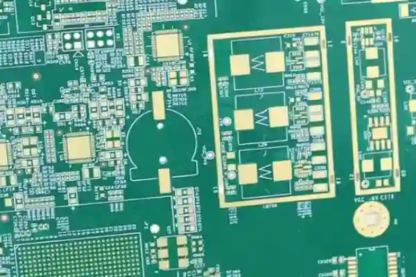
Impedance control is another easily overlooked aspect. Especially with the widespread adoption of industrial Ethernet, the wiring requirements for differential signals are becoming increasingly stringent. I’ve seen many board manufacturers make inconsistent spacing between differential pairs to meet deadlines, resulting in severe signal reflection. Later, we mandated that suppliers provide impedance test reports before each production run. Although this increased the cost, we haven’t experienced any production line downtime due to packet loss since.
An even more absurd experience: a batch of PLCs frequently malfunctioned under high temperatures. Upon disassembly, we found that the shielding via density next to the ADC sampling circuit was insufficient, like leaving a loosely closed window for delicate signals. Later, we directly installed two rings of vias around the simulation area, reducing the spacing to 1 millimeter, which completely solved the problem. These seemingly insignificant manufacturing details accumulate to become the watershed for equipment reliability.
Ultimately, the stability of a PLC doesn’t rely on some fancy design technique, but on end-to-end control from PCB material selection to etching precision to soldering processes. Sometimes, spending days adjusting parameters is less effective than switching to a reliable PCB manufacturer.
The environmental conditions of industrial sites are indeed a severe test for electronic equipment. I’ve seen too many cases of equipment prematurely scrapped due to improper PCB material selection. Circuit boards that functioned perfectly in the office developed numerous problems as soon as they arrived in the factory workshop, making me realize that ordinary materials simply cannot withstand the harshness of the industrial environment.
The impact of temperature changes on circuit boards is often underestimated. I remember once inspecting equipment in a textile factory and finding cracks in the solder joints on the control board. After analysis, we found it was due to the large temperature difference between day and night in the workshop, causing the ordinary PCB substrate to repeatedly expand and contract. Only then did I truly understand the importance of high Tg materials. When the temperature exceeds a certain critical point, the substrate softens from a rigid state. This change, though invisible to the naked eye, has a significant impact on the lifespan of the circuit board. For example, in injection molding machine control systems, ambient temperatures may briefly spike above 85°C. The glass transition temperature (Tg) of ordinary FR-4 material is typically around 130°C, seemingly safe, but under long-term thermal cycling, its Z-axis coefficient of thermal expansion increases significantly, leading to via copper foil breakage. High-Tg materials (e.g., Tg ≥ 170°C) maintain better dimensional stability, with their coefficient of thermal expansion (CTE) changing more gradually in high-temperature regions, effectively suppressing microcracks caused by thermal stress. These materials also have a higher density of molecular cross-links, acting like more support points for the circuit board’s framework, allowing it to maintain structural integrity even under drastic temperature fluctuations.
Electromagnetic interference is also a significant issue. Interference generated by the start-up and shutdown of large motors can cause fragile control systems to malfunction. I prefer to choose specially treated PCB substrates to address this problem rather than simply relying on post-construction shielding. After all, a weak foundation makes subsequent remedial efforts much less effective. Specifically, substrates with low dielectric constant (Dk) and low loss factor (Df) can be used, such as polytetrafluoroethylene (PTFE) or ceramic-filled hydrocarbon resin systems. These materials can reduce electromagnetic energy loss and coupling during signal transmission, reducing sensitivity to high-frequency interference at the source. In practical inverter control board applications, circuit boards using these substrates exhibit significantly better signal integrity than those using standard materials, and even when near high-power cable wiring, the bit error rate can be controlled within acceptable limits. This is equivalent to building the first electromagnetic defense line inside the circuit board, which, combined with proper grounding and shielding layers, forms multi-layered protection.
The corrosion of circuit boards by moisture and corrosive gases is gradual. Once, during the disassembly of equipment that had been in service for many years, it was found that although the components were still intact, the PCB had already shown slight corrosion. This reminds us that environmental adaptability must be considered when selecting materials. Different types of substrates perform very differently in terms of moisture and corrosion resistance, requiring selection based on the specific application scenario. For example, in electroplating workshops or chemical plants, the air often contains corrosive components such as chloride ions and sulfides. The epoxy resin matrix of standard FR-4 may hydrolyze, leading to a decrease in insulation resistance. Substrates using special curing systems (such as dicyandiamide substitutes) or coated with a dedicated moisture-proof coating (such as parylene) can significantly improve chemical resistance. The principle is to form a denser, highly cross-linked network that blocks the penetration of moisture and corrosive media. I once compared two identically designed circuit boards used in a coastal power plant: one using ordinary materials developed green copper rust after three years; the other, using a highly moisture-proof substrate, remained in good condition after five years, demonstrating the crucial role of initial material investment in long-term reliability.
The reliability of circuit boards under vibration environments tests the overall design, not just the component soldering quality. The rigidity of the substrate directly affects the ability of solder joints to withstand mechanical stress. Ordinary FR4 materials often fail to meet these requirements. For example, in mining machinery or rail transportation equipment, continuous low-frequency vibration and occasional impacts are common. Ordinary FR-4 has limited bending strength; under long-term vibration, the board itself will undergo slight deformation, which will be transmitted to the solder joints, leading to fatigue fracture. Boards using high-rigidity substrates, such as metal-based (aluminum or copper-based) or thick copper foil (e.g., 3 oz or more), have a higher modulus of elasticity, effectively suppressing board vibration amplitude. Just like reinforced concrete is more earthquake-resistant than ordinary brick walls. In actual engine control units (ECUs), circuit boards using high-rigidity substrates show an order of magnitude lower solder joint failure rate for large BGA-packaged chips compared to those using standard materials, because the substrate distributes most of the mechanical stress, providing a stable support platform for precision solder joints.
Every time I see those neatly arranged circuit board production lines, I always think about one question—why do we always focus on post-processing? In fact, many problems are already foreshadowed in the design phase. Take the component layout on a PCB, for example.
I’ve seen too many engineers haphazardly mix connectors and chips. Only when applying conformal coating do they discover the masking tape is crooked and uneven. Even worse, some connector metal contacts will experience poor contact once the coating gets on them. Rework at this point is a disaster.
Later, we changed our approach. When designing PCBs, all external interfaces are concentrated at the board’s edge. This not only facilitates precise spraying by robotic arms on the production line but also reduces the amount of masking material used. Sometimes, a simple layout optimization can increase production efficiency by more than 30%.
Regarding quality control, I’ve noticed many people over-rely on UV inspection lamps. While fluorescent agents can indeed help us quickly identify missed areas, the truly crucial step is pre-spraying preparation. For example, protecting the gold fingers with a transparent film beforehand or applying a special protective film to the heatsink—these seemingly trivial steps actually ensure the final result.
I was once impressed by the practices of an automotive electronics factory we visited. Each production line was equipped with an automatic identification system that could adjust the spraying path in real time through visual inspection. As the PCB on the conveyor belt passed by, it automatically scanned the board surface, marked the locations of connectors that needed protection, and then controlled the spray nozzles to intelligently avoid them.
However, what impressed me most was their attention to detail. Every operator clearly understood the specific requirements of different PCB models; for example, the communication interface of a certain industrial PLC required a 2mm uncoated area. This accumulated experience is far more reliable than simply relying on inspection equipment.
Looking back, those obsessions with perfect coating uniformity might actually be stumbling blocks to efficiency. After all, the ultimate mission of a circuit board is stable operation, not just aesthetics. Sometimes leaving appropriate blank space around connectors is more practically valuable than striving for full coverage.
I’ve always felt that articles that portray industrial automation as something incredibly sophisticated are somewhat detached from reality. Last week, seeing an old machine still running in the workshop suddenly made this thought pop into my head—the PLC used in that machine had been working for almost twenty years. Engineers these days love to discuss concepts like Industry 4.0 or digital twins, but what truly interests me are the fundamental issues that are often overlooked.
Many people don’t realize that designing a typical consumer electronics product and designing an industrial PCB are completely different things. If the circuit board in your phone breaks, you just replace it, but if the PLC controlling the production line malfunctions, the entire workshop might have to shut down. This pressure directly impacts your design thinking.
I’ve seen too many young engineers apply their experience designing consumer-grade circuit boards to PLC projects, only to have their first batch of prototypes fail in the harsh workshop environment. One case is particularly typical: their designed circuit board worked perfectly in the lab, but frequently crashed in the factory. It was later discovered that the wiring hadn’t considered interference from motor start-stop, and several critical signal lines were run too close to the power supply.
In fact, industrial environments place extremely practical demands on PCBs. Factors like humidity, dust, and temperature fluctuations must be considered during the design phase. Once, when testing a newly designed PLC circuit board, we deliberately placed it near a heat source and ran it continuously for 72 hours. This seemingly clumsy testing method actually helped us discover several potential thermal management issues.
Material selection is also an easily underestimated aspect. Ordinary FR-4 board performs well in mild environments, but in workshop environments with corrosive gases, more specialized substrates are needed. Although the cost is higher, considering the equipment might run continuously for over a decade, this investment is entirely worthwhile.
Looking back at that 20-year-old piece of equipment, its PCB design wasn’t particularly fancy; it simply implemented all the necessary protection measures meticulously. This simple design approach has stood the test of time. Sometimes I feel that instead of chasing the latest technological concepts, it’s better to solidify the fundamentals first. After all, in the industrial field, reliability is always more important than fashion.
I’ve always found industrial-grade PCB design particularly interesting. Many people might think it’s just drawing circuit boards, but it’s not that simple. Take a recent project I worked on, for example.
Our team was discussing which surface treatment process to choose for a PLC board used in an industrial environment. Someone suggested immersion silver because it’s cheaper! But I strongly opposed it.
Think about it, how complex is the industrial environment? Various chemical gases, humidity fluctuations, temperature fluctuations… Immersion silver is particularly prone to problems in such environments. Over time, silver sulfide whiskers will form on the surface. These may seem insignificant, but they can slowly extend on the board, causing short circuits! This is a problem I’ve personally witnessed. Later, we switched to nickel-palladium immersion gold, which was more expensive, but the stability was much better.
Another time that left a deep impression on me was the application of crimping technology.
When we were designing a backplane requiring highly reliable connections, we initially considered soldering, but later found that crimping was more suitable for this scenario. It avoids the thermal shock issues associated with soldering, causing significantly less damage to the board, and also offers higher mechanical strength.
However, crimping places extremely high demands on the PCB! Especially the hole diameter tolerance, which must be controlled within a very small range; otherwise, the terminals will either be too loose for poor contact or too tight, cracking the hole walls.
Speaking of the hole wall issue, I have a lot of experience with it.
Once, during sample testing, we found micro-cracks in the copper layer of some holes. Analysis revealed this was due to insufficient copper thickness and inadequate ductility. Since then, we’ve paid special attention to this detail. Now, when making these types of boards, we require a minimum copper thickness of 30 micrometers for the holes, and we always use a high-ductility electroplating process.
Actually, I think the most important thing in making industrial-grade products is this kind of meticulous attention to detail.
Many people might think these requirements are too demanding, but you have to understand that if industrial equipment malfunctions, it can affect the entire production line. Therefore, when designing, we’d rather spend more money and effort to prioritize reliability.
By the way, speaking of reliability, I also want to mention the conformal coating process.
This truly gives the PCB an invisible protective armor! I remember a project in a chemical plant where we chose polyurethane for the coating. Although rework was indeed more troublesome, its chemical corrosion resistance was exceptional, making it particularly suitable for that environment.
Of course, different applications require different coating materials. For example, in high-temperature environments, silicone materials might be considered, although they are expensive, they are worthwhile.
My biggest takeaway from so many years in this industry is: good PCB design isn’t about excelling in a single aspect, but about perfecting every detail. From material selection to process control, from front-end design to back-end processing, every step is interconnected to create a truly reliable product.
I’ve seen far too many people focus excessively on sophisticated algorithms when discussing PLC design, neglecting the most fundamental element—PCB quality. This is as dangerous as building a house without a foundation. Once, I took on a project where the client complained of fluctuating temperature readings. After checking the program thoroughly, we found the problem lay with a small analog input module on the PCB. In a humid environment, the insulation of a poor-quality solder mask deteriorated, causing a small leakage current that directly ruined the accuracy.
In fact, industrial environments place far more stringent demands on PCBs than we imagine. Do you think choosing green ink guarantees good insulation? Those seemingly insignificant details often determine the fate of the entire system. I remember a case at a food factory where their PLC modules frequently failed in a humid workshop. It turned out the problem wasn’t the program, but rather the poor PCB surface treatment; ordinary anti-oxidation coatings simply couldn’t withstand that environment.
Many people think gold plating is just for aesthetics when it comes to connection technology. But in the PLC field, it’s a genuine guarantee of performance. Especially the gold finger contact points between modules; ordinary surface treatments might wear down after only a few dozen insertions and removals. I prefer the hard gold process, even though it’s more expensive. But considering the production lines that require frequent module replacements, the investment is well worth it.
Modal design is an advantage of PLCs, but it also places higher demands on the PCB. Signal transmission between modules must be absolutely precise. Once, during debugging, I discovered that a digital module was unstable; the root cause turned out to be a tiny scratch on the backplane PCB causing intermittent contact problems.
Cleanliness is often underestimated. A chemical plant’s PLC system kept experiencing inexplicable problems, which were eventually discovered to be flux residue left during PCB assembly forming a micro-battery effect in a corrosive gas environment. This kind of hidden danger is impossible to detect with ordinary testing.
Ultimately, the reliability of industrial-grade PLCs isn’t built on a few cool features, but rather on meticulous attention to detail in every PCB. Those seemingly insignificant process choices often become the cornerstone of stable system operation at critical moments.
Circuit boards are more than just that green board in a phone
From disassembling old routers to visiting electronics manufacturing plants, I gradually realized
As an electronics enthusiast, I’ve come to understand firsthand the impact of
• Expert in Small-to-Medium Batch Production
• High-Precision PCB Fabrication & Automated Assembly
• Reliable Partner for OEM/ODM Electronic Projects
Business Hours: (Mon-Sat) From 9:00 To 18:30