
How Do PCBs for Medical Devices Hold the “Last Line of Defense for Life”?
In the field of medical electronics, attention often focuses on complex algorithms;
I have long felt that many people’s understanding of “high density” is merely superficial. They often assume that simply making the circuit traces thinner constitutes the entirety of the concept. In reality, true high-density design is much more akin to playing a game of spatial planning. You must carefully consider how signals are routed to prevent them from interfering with one another. You must determine how heat can be effectively dissipated to prevent chips from overheating and burning out. Furthermore, you must anticipate whether those minuscule spacing tolerances will lead to issues during the manufacturing process.
I recall a specific project where I was responsible for designing a high-density circuit board. Initially, I, too, believed that simply ensuring sufficient wiring density would suffice. However, when the first batch of prototypes returned, we discovered severe signal crosstalk issues. It was only later that we realized the problem stemmed from flaws in the ground plane layout. Such details often prove far more critical than the trace widths themselves. For instance, in high-speed digital circuits, an improperly routed ground return path can trigger electromagnetic compatibility (EMC) issues; even if the trace widths are reduced to the micron level, the overall system performance may still be severely compromised. This situation is analogous to constructing a skyscraper while focusing solely on the floor area of the rooms, yet completely overlooking the distribution and placement of the load-bearing walls.
The greatest test in high-density design is foresight. You must anticipate every potential scenario that could arise during the manufacturing phase. Examples include the alignment precision required between the layers of a multi-layer board, or the differential thermal expansion coefficients of various materials when subjected to high temperatures. These seemingly unrelated factors can—and often do—impact the final outcome. Take the common FR-4 substrate material as an example: its coefficient of thermal expansion along the Z-axis is approximately three times that of copper. If this disparity is not properly accounted for during the reflow soldering process, it can lead to fractures within the vias (plated-through holes). The precision of laser drilling technology can now reach ±15 microns—a level that imposes extremely rigorous demands on interlayer alignment for boards comprising ten or more layers.
I have seen far too many teams focus exclusively on technical parameters while neglecting overall balance. They chase after the absolute minimum line width, yet forget to account for thermal dissipation requirements. Alternatively, they sacrifice testability in the pursuit of miniaturization. Consequently, when the product enters mass production, the yield rate consistently fails to rise. Some companies specifically develop simulation models to predict current and thermal distribution in advance—essentially creating a “thermal map” for the circuit—thereby preventing localized overheating. The placement of test points, in particular, requires strategic planning; for instance, when utilizing boundary scan technology, a mere 0.5mm deviation in test point spacing can result in a 20% drop in test coverage.
The true allure of high-density design lies in the fact that it compels you to approach problems with a systems-thinking mindset. You cannot simply stare at the circuit schematics; you must also understand material properties, manufacturing processes, and even the end user’s specific operating environment. This interdisciplinary approach to thinking often yields unexpected innovations. Consider the design of circuit boards for medical endoscopes: one must simultaneously account for biocompatible coatings, the mechanical limits of flexible substrates, and the resistance to chemical corrosion during sterilization procedures.
Sometimes, a willingness to slightly compromise on certain density metrics can actually result in superior overall performance. This is akin to urban planning: a city is not deemed successful simply because its buildings are packed together as densely as possible; rather, adequate public spaces must be preserved to allow the city to “breathe.” In the realm of chip packaging, a design strategy that deliberately incorporates “thermal buffer zones” often results in a product lifespan that is three times longer—or more—than that of a design that attempts to fill every last millimeter of the silicon die. These lessons are particularly evident in the aerospace sector, where redundant design is sometimes favored over extreme miniaturization.
A truly excellent high-density design ensures that every component is situated exactly where it needs to be, that signal traces are routed with maximum efficiency, and that sufficient margin is preserved for both manufacturing and maintenance. Cultivating this sense of balance requires a great deal of time and practice. For instance, in microwave circuit design, transmission line corners are typically routed as smooth arcs rather than sharp right angles; although this consumes slightly more real estate, it effectively minimizes signal reflection. This design philosophy is reflected in numerous details: decoupling capacitors must be placed in close proximity to power supply pins, and high-frequency signal traces must avoid running parallel to one another for distances exceeding a specific threshold.
Nowadays, whenever I embark on a new project, I begin by asking myself: Is this level of density truly necessary? Is there a more elegant solution available? After all, the best design is not necessarily the densest one—it is the one that is most appropriate for the task at hand. Just as the latest wearable devices are beginning to adopt 3D stacking technology—enhancing functional density by utilizing vertical space—this approach proves far more ergonomic than simply compressing components onto a two-dimensional plane. This shift in mindset often stems from a deep, fundamental reflection on the true essence of a product.
Whenever I look at those densely packed, high-density circuit board schematics, a question always crosses my mind: Are we becoming too fixated on simply making things smaller? The industry today is constantly abuzz with discussions about achieving 0.05mm trace widths or drilling microscopic vias; yet, rarely does anyone stop to ask whether doing so is truly worth the effort.
I recall a project last year where a client insisted that we push the circuit routing to its absolute physical limits. The result? Once the boards were manufactured, heat dissipation became a major issue; temperatures would skyrocket the moment the system ran under a high load. We ultimately had to redesign the board—a process that cost us two months of delays. Sometimes, the relentless pursuit of extreme physical density leads us to overlook the critical importance of stability in real-world applications.
In reality, circuit board density should be viewed as a holistic concept. Much like urban planning—where one cannot simply focus on how densely buildings are packed without also considering essential infrastructure like traffic flow, water supply, and power grids—every trace and via on a circuit board exists within a three-dimensional space where elements constantly interact with one another. Fixating solely on numerical trace width specifications makes it all too easy to find oneself in a technological dead end.
I have encountered numerous engineers who, in an effort to squeeze traces beneath a BGA package, would push trace widths down to a mere 0.06mm. Yet, in practice, slightly relaxing that constraint to 0.08mm could boost manufacturing yields by 30% and simultaneously lower production costs. Such a pragmatic compromise can, paradoxically, make the final product even more competitive.
Many manufacturers today love to tout the high levels of integration they have achieved, yet they rarely mention the sacrifices made to attain that density—sacrifices involving signal integrity, thermal efficiency, or even the product’s reparability. During a teardown analysis of a certain brand’s flagship product, we discovered that in order to cram in more features, they had utilized an eight-layer stack-up featuring arbitrary-layer blind vias. Consequently, the motherboard became highly susceptible to delamination and cracking whenever it was subjected to even minor external physical stress.
I believe that true technological breakthroughs should not be measured solely by physical compression, but rather by how intelligently we can arrange components and routing within finite spatial dimensions. Sometimes, simply tweaking the placement of components or optimizing power delivery paths yields far superior results than obsessively shaving off a few tenths of a millimeter from a trace width. Of course, I’m not suggesting that high-density design is unimportant; I simply feel the industry needs a more balanced perspective. We must acknowledge that in certain scenarios, a traditional 0.1mm trace width—combined with a sensible layer stackup—is actually more practical than blindly chasing extreme limits. After all, a circuit board is ultimately meant to be installed and used within a product, not placed under a microscope for a competition.
Lately, I’ve been experimenting with a hybrid approach: using fine traces for critical signal paths while maintaining standard dimensions for general power sections. This strategy ensures performance while keeping costs in check—a direction that may well be more worth exploring in actual engineering practice.
I’ve been giving a lot of thought to high-density circuit boards recently. I used to assume that the job was done simply by making the traces thinner and denser; as it turns out, that couldn’t be further from the truth.
I remember one instance where our team designed a board absolutely packed with chips. At first, we were quite proud of ourselves, thinking we had achieved incredibly high space utilization. However, during testing, we were nearly scared to death: the temperature in one specific area suddenly skyrocketed to nearly 100°C. When we later disassembled the board to investigate, we discovered that the heat was entirely trapped beneath the chips, unable to dissipate.
That incident taught me a valuable lesson: the biggest headache in high-density design isn’t how to cram in more components, but rather how to ensure heat can be efficiently channeled away. Just think about it: the dielectric layers are so thin that their thermal conductivity is inherently limited; add to that the fact that the copper foil in fine traces is also quite thin, and it’s hardly surprising that heat tends to accumulate.
Nowadays, thermal management is a top priority whenever I’m designing. For instance, I make sure to leave ample clearance around the chips—even if it means sacrificing a bit of density—to guarantee effective heat dissipation. Sometimes, I’ll even deliberately scatter high-heat-generating chips across the board to prevent them from clustering together and heating each other up.
Thermal management is actually quite a fascinating subject. I’ve noticed that some engineers tend to rely heavily on stacking up heatsinks, yet they often overlook the fundamental design of the thermal conduction path itself. Much like how you need to lay a solid foundation before building a house, if the basic thermal infrastructure of a circuit board isn’t properly established, adding extra cooling measures later on will yield only half the results for twice the effort.
On one occasion, we experimented with embedding copper blocks directly into the board. The results were indeed impressive, but the cost proved to be prohibitively high. Ultimately, we reverted to a more fundamental approach, resolving our thermal issues by optimizing the layout of vias and the distribution of copper planes. It may not be as flashy or high-tech, but it is both practical and cost-effective.
When all is said and done, designing high-density circuit boards is essentially a balancing act. In a confined space, one must balance electrical performance with thermal management requirements—all while keeping practical manufacturing feasibility in mind. Sometimes, to ensure effective heat dissipation, we are compelled to make the PCB slightly thicker or sacrifice a degree of routing density.
I’ve developed a habit now: before I even start laying out a board, I first visualize exactly how the heat will flow. After all, no matter how powerful a chip may be, it would be a tremendous waste if its performance were throttled—or worse, if it suffered permanent damage—due to thermal issues.
The longer I work in this field, the more I realize that truly good design isn’t about blindly chasing maximum density, but rather about finding the optimal balance point. Ultimately, circuit boards are meant to be used; they aren’t merely artifacts designed to showcase technical prowess.
I recently dug out an old mobile phone I used a decade ago. When I popped off the back cover and examined the PCB layout inside, I found it fascinating. The designs of that era still featured plenty of unused “whitespace,” and the spacing between traces was quite generous. Comparing it to the motherboard inside the new device currently in my hand, it feels like looking at objects from two entirely different worlds.
Engineers working on high-density PCBs can surely relate: this style of design has completely transformed our workflow. In the past, one might have simply needed to ensure components were placed logically; now, we have to think like urban planners. Every square centimeter demands meticulous calculation, and the routing of traces must be orchestrated with the same precision one would apply to designing a city’s transportation network.
I recall a project where our team spent an entire afternoon debating how to save a mere 0.1 millimeters of space. It might sound like an exaggeration, but in the context of actual design, that tiny sliver of space often serves as the critical threshold—determining whether or not we can squeeze in a vital component. This relentless pursuit of spatial efficiency reminds me of the intense, high-stakes feeling one gets while playing Tetris.
Thermal management becomes a particularly thorny issue in high-density designs. When components are packed too closely together, heat tends to accumulate. During one round of testing, we detected an abnormally high temperature on a specific chip; after troubleshooting, we discovered that a newly added adjacent module was disrupting the airflow. This is the kind of problem that simply wouldn’t arise on a board with standard component density.
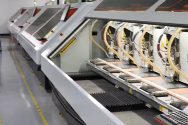
The challenges on the manufacturing front are equally substantial. As trace widths shrink ever thinner, the demands placed on production processes and precision rise commensurately. A veteran technician at one of our partner factories often remarks that fabricating PCBs these days requires the same meticulous care and precision as doing fine embroidery. Indeed, even a minor oversight can easily compromise an entire production batch.
That said, these very challenges also serve as powerful catalysts for technological advancement. The emergence of many new materials and manufacturing processes we see today is, in fact, a direct response to the myriad complex issues introduced by the era of high-density design. Just as smartphones once drove the advancement of touchscreen technology, demand remains—as always—the ultimate catalyst for innovation.
Looking at today’s exquisitely crafted circuit boards, I find myself feeling a twinge of nostalgia for the somewhat rugged design aesthetics of the past. Yet, such is the nature of technological evolution: it is a ceaseless journey toward making things smaller, faster, and more powerful. As a professional in this field, being able to participate in this ongoing process is truly a fascinating experience.
I have seen far too many teams stumble when it comes to high-density circuit board design. They often operate under the misguided assumption that simply routing traces as densely as possible equates to a design victory; consequently, when the prototypes return, they discover that either impedance control has gone haywire or thermal management has completely collapsed.
On one occasion, while reviewing a smart wearable project for a friend, I encountered a design utilizing an 8-layer “any-layer interconnect” structure with trace widths squeezed down to a mere 0.05 millimeters—it looked incredibly impressive. However, the very first batch of samples exhibited significant signal crosstalk. We later discovered the root cause: a failure to account for variations in the dielectric constant of the PCB substrate material. Issues like this are impossible to detect merely by poring over datasheets; one must conduct actual impedance testing to truly understand and characterize the underlying behaviors.
I now place immense value on the simulation phase of the design process. I am not referring to perfunctory, checkbox-ticking simulations, but rather a rigorous approach that treats the circuit board as a living, dynamic system. Take Power Integrity (PI) issues, for instance: simply analyzing DC voltage drop is insufficient; one must also simulate the transient response under dynamic load conditions. On one project, our PI simulations revealed a “blind spot”—an area with inadequate power delivery—within a specific BGA package. By promptly adjusting the layout of the decoupling capacitors, we successfully averted the need for costly rework later in the development cycle.
The testing phase, too, demands a departure from conventional thinking. High-density boards cannot simply be tested after final assembly; they require a layered, incremental verification process. We begin with micro-section analysis of the bare board to validate the quality of the plated-through holes; next, we individually test the signal integrity of critical networks; and finally, we proceed to full system-level functional verification. While this progressive testing methodology is admittedly time-consuming, it enables us to pinpoint the root causes of issues early in the process.
In truth, the aspect most frequently overlooked is thermal management. As trace density increases, the pathways available for heat dissipation become increasingly complex. On one project, measurements revealed that the localized temperature on a specific high-density board was running 15 degrees higher than anticipated; we ultimately resolved the issue by utilizing thermal simulations to redesign and optimize the array of thermal vias. Consequently, I now make it a standard practice in my designs to incorporate a 20% thermal margin.
Ultimately, a high-density circuit board is not merely a stage for technical virtuosity, but rather an intricate art form—a delicate balancing act performed amidst the various physical limits of the material world. Sometimes, by taking a step back and adopting slightly more relaxed spacing, one can actually achieve superior overall reliability.
I recently discussed PCB design trends with several hardware engineer friends and realized that our collective understanding of “high density” has evolved significantly. In the past, high density was simply equated with making traces as fine and tightly packed as possible; looking back now, that perspective seems somewhat outdated.
A project I worked on serves as a perfect illustration of this point. At the time, the client insisted on pushing trace widths to their absolute physical limits. Consequently, when the first batch of boards returned for testing, we encountered a ceaseless stream of signal integrity issues. We subsequently shifted our focus to optimizing the overall board layout—and, ironically, achieved superior performance by utilizing more relaxed trace spacing. This experience taught me that the true essence of high-density PCB design lies not in how tightly components are crammed together, but rather in how effectively the signals are facilitated to flow smoothly.
When the topic of HDI (High-Density Interconnect) technology arises, many people’s first instinct is to focus on just how small micro-vias can be made. In reality, the true test of expertise lies in establishing an efficient interconnection network across the various layers of the board. I have seen designs where, in a quest for impressive technical specifications, micro-vias were packed too densely—a choice that actually increased the risk of impedance mismatches.
I am now much more optimistic about design approaches that prioritize flexibility. For instance, this might involve slightly relaxing routing density in areas with high thermal dissipation requirements, while employing an interleaved layout strategy in areas with high signal density. Boards designed with this philosophy may not appear to be the most compact at first glance, but their actual performance often proves to be far superior.
During a visit to a medical device manufacturing facility, I observed a particularly fascinating approach to PCB layout. Instead of blindly pursuing absolute minimization, they allocated space based on the functional importance of each module. Critical signal paths were allotted ample headroom, while high-density integration was reserved for secondary areas. This philosophy is well worth emulating: high density should be treated as a means to an end, not an end in itself.
As chip integration levels continue to rise, our fundamental concepts of PCB design are indeed in need of an update. Simply fixating on numerical parameters—such as trace widths and via diameters—is no longer sufficient; it is far more critical to understand how current flows, how heat dissipates, and how signals propagate. Sometimes, by slightly relaxing density constraints in specific areas, one can actually achieve a superior overall outcome.
I believe that future high-density designs will place an increasing emphasis on customization. Different application scenarios demand distinct density strategies; for example, wearable devices may require full functionality within an extremely confined space, whereas industrial equipment prioritizes long-term operational stability. There is no single “one-size-fits-all” solution; the key lies in identifying the optimal balance point that precisely meets the specific requirements at hand.
As I look at how the traces on circuit boards are becoming increasingly fine, I actually find myself beginning to miss the more spacious layouts of earlier years. This isn’t to suggest that technology has regressed; rather, I feel that sometimes—just sometimes—it is quite important to leave a little “breathing room” for the circuitry. After all, electronic devices are much like living organisms: they, too, require adequate room to maneuver in order to maintain their optimal state.
Spend enough time in this field, and you’ll discover that the finest designs are rarely those boasting the most impressive technical specifications; rather, they are the ones best adapted to the realities of their operating environment. Ultimately, a high-density circuit board is merely a substrate—a vessel. What truly matters is its ability to enable the electronic components housed within to coexist in perfect harmony. It is akin to urban planning: the goal isn’t simply to erect the tallest buildings possible, but to create an environment where people can live comfortably.
I often find myself reflecting whenever a new high-density fabrication process emerges. While technology is indeed constantly pushing the boundaries of physical limits, we designers must remain clear-headed: Why, exactly, are we pursuing such high density? If we lose sight of this fundamental purpose, even the most advanced technology risks devolving into nothing more than a meaningless numbers game.
At its core, circuit board design is the art of balance. It involves orchestrating countless interconnected nodes within a finite space—much like positioning pieces on a chessboard, where one must consider not only the immediate move but also the strategic implications for future developments. This sense of dynamic equilibrium may well be more critical than any specific technical metric.
Occasionally, while poring over circuit schematics from a decade ago, I stumble upon fascinating details. Although the manufacturing capabilities of that era were limited, the ingenuity evident in those layouts remains remarkably relevant today. Perhaps that is the true allure of design: while technology inevitably becomes obsolete, the pursuit of excellence in design remains an enduring constant.
Whenever I gaze upon those densely packed schematics for high-density circuit boards, a single question invariably crosses my mind: Have we become too obsessed with the relentless drive to make everything smaller? I recall a project last year where, in pursuit of extreme thinness and lightness, three major chips were crammed into an area no larger than a fingernail. During testing, however, we discovered that the power supply would trigger an alarm after just ten minutes of operation. We later traced the issue to inadequate heat dissipation; the cooling system simply couldn’t keep pace with the current fluctuations, causing the entire system to become unstable.
In reality, many people overlook a fundamental fact: the higher the current, the greater the heat generated—and high temperatures cause chip performance to plummet. I have encountered far too many cases where designers, in an effort to save space, placed decoupling capacitors a considerable distance away from the chips. Consequently, during high-frequency operation, the power supply ripple became so severe that it interfered with signal transmission. This is akin to fitting a high-performance sports car with a leaking fuel tank; no matter how excellent the engine is, it simply cannot unleash its full potential.
On one occasion, I helped a friend modify a drone flight controller board. They had originally used standard 1-ounce copper foil, but they experienced severe voltage drops whenever high currents flowed through the board. I subsequently laid down a localized patch of 2-ounce thick copper along the power supply path. Although this increased the board’s thickness by a mere 0.1 millimeters, the chip temperature dropped by a full 15 degrees during full-load flight. Sometimes, solving a problem doesn’t necessarily require stacking more layers; the key lies in truly understanding the specific path the current is taking.
Nowadays, some manufacturers love to boast about how many components they can cram into a multi-layer PCB, yet very few dare to publicly disclose the actual effectiveness of their thermal management solutions. I once worked on a smart home device… The main control board in question integrates five processors—a fact the manufacturer touted extensively in their marketing—yet they failed to mention, even in passing, the necessity of installing an auxiliary active cooling fan. It was only when users actually put the device to use that they discovered, in a quiet environment, the fan noise was louder than that of an air conditioner. Fundamentally, this design amounts to nothing more than offloading the problem onto the consumer.
What I find truly frustrating is the emergence of a peculiar set of values within the industry: it seems that whoever manages to pack components most densely onto a board is automatically deemed the technological leader. Yet, consider industrial-grade equipment—why does it reliably last for eight or ten years? Because manufacturers are willing to allocate ample headroom for power supplies, utilize thicker copper traces, and even incorporate dedicated thermal management modules. While mobile devices certainly require a trade-off regarding physical size, they should at least make users aware of the costs associated with “high-performance mode,” rather than waiting until the phone becomes scalding hot before triggering a frequency reduction.
Recently, we experimented with using embedded copper blocks to dissipate heat from chips in a smartwatch project. Although the initial prototyping costs were somewhat higher, we encountered absolutely no instances of overheating or system crashes during the testing phase. A colleague jokingly remarked that the design made the chip look as if it were wearing a down jacket. In reality, the principle is quite simple: heat must be effectively extracted to ensure stable current flow; otherwise, even the most sophisticated circuitry remains nothing more than a castle in the air.
While recently observing a sample of a high-density circuit board in the lab, I suddenly realized that this technology is something entirely different from what we typically imagine. I used to assume that “high density” simply meant cramming more components onto a board; now, however, I realize the true challenge lies in ensuring that these tightly packed traces can function correctly without interference. This is particularly critical when AI chips are tasked with processing massive datasets; the dense web of traces begins to resemble a city’s subway network during rush hour—a scenario where even the slightest misstep can lead to mutual interference.
I recall a specific testing session where we repeatedly encountered signal transmission anomalies; we eventually traced the issue back to the substrate material itself. In a high-frequency environment, traditional FR-4 material behaves much like an aging road—riddled with potholes and uneven surfaces. This experience led me to consider a shift in perspective: rather than merely patching up the existing foundation, perhaps we should fundamentally change the material we use. Glass substrates, for instance, present a fascinating alternative; their near-perfect flatness effectively creates a “superhighway” for signal transmission.
However, to be honest, I feel the industry’s current obsession with density has gone a bit too far. I have witnessed far too many manufacturers, in their relentless pursuit of so-called “ultra-high density,” inadvertently overlook the critical importance of stability in real-world applications. Much like constructing a skyscraper, one cannot simply focus on achieving maximum height without first ensuring the foundation is solid and secure. Sometimes, slightly reducing density can actually lead to greater overall system stability. This is particularly true in fields with extremely high reliability requirements—such as medical equipment—where it is far better to err on the side of caution than to take unnecessary risks.
As for future trends, I personally don’t believe 3D printing will become the mainstream direction. While it sounds impressive in theory, its stability in practical applications remains a persistent issue. Instead, breakthroughs in materials science—such as novel substrate materials capable of self-repairing microscopic damage—strike me as far more promising and worthy of anticipation.
Ultimately, the essence of high-density design lies not in how many components can be crammed into a space, but rather in how those components can be made to coexist harmoniously. It is much like effective urban planning: the goal isn’t simply to build structures as densely as possible, but to create an environment where people can live comfortably. The same principle applies to circuit design: no matter how high the density, the quality of signal transmission must remain uncompromised. After all, we are creating practical products, not exhibits for an art gallery.
I’ve long felt that current discussions surrounding high-density circuit boards have gone somewhat off track. People tend to get fixated on the idea that the sole purpose is to minimize board size and boost performance metrics. In reality, what matters most to me are the trade-offs and compromises inherent in the design process itself.
I recall working on a project that required a high-density circuit board solution. At the time, a faction within the team insisted on pushing every trace to the absolute limit—adopting the narrowest possible line-width standards. Consequently, during the testing phase, we encountered persistent stability issues with certain high-frequency signals. We eventually discovered that this was caused by excessive interference between adjacent traces—a direct result of our overzealous pursuit of wiring density.
Sometimes I find myself wondering if we’ve become too fixated on technical parameters. While it is true that modern manufacturing processes allow for incredibly fine line widths, this does not imply that such extreme specifications are necessary for every scenario. This is especially true when a product is cost-sensitive; in such cases, it is often more prudent to appropriately relax certain design requirements.
I’ve observed many engineers who habitually apply the very latest manufacturing processes to every single project they undertake. For instance, they might insist on using mSAP technology for standard consumer electronics, even though conventional HDI technology would be more than sufficient to meet the requirements. An excessive pursuit of technical benchmarks can actually drag an entire project into a quagmire of unnecessary complexity.
What truly matters is understanding the product’s positioning and its actual functional requirements. If you are designing medical equipment or aerospace hardware, then by all means, you should spare no expense in adopting the most sophisticated design solutions available. However, if you are working on standard home appliances, your primary focus should likely be on manufacturing stability and cost control.
A particularly interesting phenomenon I’ve noticed recently is that an increasing number of clients are now proactively requesting that we lower the density specifications for their circuit boards. They discovered that slightly increasing the board area actually led to a significant reduction in production costs and a higher yield rate. I believe this pragmatic attitude is particularly worthy of emulation.
Ultimately, technology serves the product—not the other way around, where the product is forced to compromise to accommodate technical specifications. Whenever I design a new board, I first ask myself: Does this product really require such high density? How stringent are the actual signal transmission requirements? Clarifying these fundamental questions often leads to a more appropriate and effective design solution.
Currently, there is an unfortunate trend in the industry: the blind pursuit of maximum technical parameters, while ignoring the nuances of real-world application scenarios. I believe a truly excellent engineer possesses the ability to flexibly adapt design solutions based on specific requirements, rather than simply applying standard templates.
Sometimes, slightly relaxing trace width requirements to ensure adequate safety margins between signal lines can actually result in more stable overall performance. Such seemingly conservative choices often prove to be the wisest decisions; after all, reliability is the lifeline of any electronic product.
I have seen far too many teams stumble when designing high-density circuit boards. They often mistakenly believe that pushing trace widths to their absolute limits is the hallmark of technological leadership, while overlooking the practical challenges faced on the manufacturing floor.
I recall a medical equipment client we worked with last year who insisted on a trace width of just 0.04mm. Consequently, the yield rate for the first batch of boards fell below 60%. The veteran technicians at the factory just shook their heads, remarking that attempting to achieve such parameters with their existing equipment was essentially a gamble. Later, we increased the trace width to 0.06mm; although the theoretical performance took a slight hit, the stability of the production process improved dramatically.
The handling of micro-blind vias is another specialized discipline in itself. During a visit to a production line, I observed engineers repeatedly fine-tuning their equipment to ensure precise alignment. They explained to me that the micro-blind via placements in many modern design files are often overly idealized; in actual production, the laser drilling process inevitably involves a drift of a few microns. If the underlying pads lack sufficient margin, this can easily result in open circuits.
The greatest pitfall in high-density circuit board design occurs when designers and manufacturers operate in isolation. I recommend that design teams consider the aspect ratio (thickness-to-diameter ratio) of vias right from the layout stage, rather than focusing solely on making the simulation data look impressive. Sometimes, simply adding a few extra vias or adjusting the routing density can save the factory a great deal of trouble.
Ultimately, a truly effective design strikes a harmonious balance between performance and manufacturability. The most successful case study I’ve ever encountered involved a drone company. They never pushed the parameters of their high-density circuit boards right up against the absolute limits of manufacturing capabilities; instead, they always left a sufficient safety margin. Consequently, their product iteration speed actually surpassed that of their competitors, simply because they rarely encountered issues during the production phase.
Now, whenever I review a design proposal, I always make a point of asking one extra question: “Can the factory reliably implement this specific parameter?” What seems like a simple inquiry often serves to prevent a great deal of unnecessary hassle and rework down the line.
Whenever I see those densely packed, high-density circuit board traces, I’m reminded of the troubles we faced during a project several years ago. At the time, our team was just beginning to venture into multi-layer board design; we naively assumed that simply routing the connections successfully was enough. We paid a heavy price for that assumption during the testing phase. We kept encountering persistent issues with a specific signal transmission; after hours of troubleshooting, we finally discovered that the culprit was the residual “stubs”—tiny remnants left behind inside the vias during the design and manufacturing process. These seemingly insignificant metal remnants acted like speed bumps on a highway, causing the signal to constantly reflect back upon itself.
I remember pulling several all-nighters back then just to pinpoint the root cause of the problem. When we observed the waveforms on an oscilloscope, we noticed that the signal “eye diagram”—which should have appeared crisp and clear—had become blurred and distorted. It wasn’t until we consulted with some seasoned veterans in the field that we learned a crucial lesson: when signal frequencies exceed a certain threshold, even a stub just a few millimeters long can cause significant interference. This experience drove home the realization that in high-speed circuit design, every single detail—no matter how minute—has the potential to become a performance bottleneck.
The selection of copper foil is another aspect that warrants careful consideration. Many people assume that copper thickness is a trivial matter; however, while thinner copper foil facilitates finer routing and higher density, it also results in higher electrical resistance. I’ve seen instances where designers, in their pursuit of maximum routing density, opted for ultra-thin copper foil throughout the entire board—only to suffer severe voltage drops along the high-current power paths. Later, when designing power supply modules, we made a deliberate choice to thicken the copper layers in critical areas, and the improvement in performance was immediate and dramatic. This kind of trade-off requires careful balancing based on the specific application scenario; there is no one-size-fits-all solution.
Recently, a friend of mine encountered a similar dilemma while designing the main control board for a smart home system. He initially intended to use standard manufacturing processes for all the vias, but he soon discovered that certain high-frequency signal paths required a specialized approach. After extensive experimentation, he ultimately decided to employ a “back-drilling” process for the critical signal lines; although it added slightly to the manufacturing cost, it successfully ensured signal integrity. This case study further reinforced my conviction that high-density circuit board design demands tailored, context-specific solutions rather than generic, blanket approaches. Nowadays, whenever I review a circuit schematic, I pay particular attention to the placement of vias and the planning of signal routing. Sometimes, a seemingly perfect layout scheme may harbor hidden risks regarding signal integrity—specifically, when multiple high-speed signal lines run in parallel, the likelihood of crosstalk increases significantly. These lessons have taught me that effective circuit design requires not only ensuring connectivity but also anticipating potential electromagnetic compatibility issues.
In fact, the longer I work in this field, the more I feel that PCB design is akin to playing Go: one must simultaneously maintain a global perspective and meticulously refine every local detail, as even a minor oversight in a specific area can lead to a degradation in the overall performance of the board. Recently, while experimenting with novel substrate materials, I discovered that materials with different dielectric constants can influence signal transmission speeds—a realization that has opened up entirely new avenues of thought. Perhaps this is precisely where the true allure of electronic design lies: there are always new frontiers waiting to be explored.
In the field of medical electronics, attention often focuses on complex algorithms;
After years of navigating the hardware industry, I’ve observed an interesting phenomenon:
As a practitioner in the circuit board manufacturing industry, I am keenly
• Expert in Small-to-Medium Batch Production
• High-Precision PCB Fabrication & Automated Assembly
• Reliable Partner for OEM/ODM Electronic Projects
Business Hours: (Mon-Sat) From 9:00 To 18:30