

Why the Best PCB Supply Chains Are Built Like Relationships, Not Transactions: Lessons for Satellite Communication PCB Programs
What actually makes a long-term PCB supply chain partnership work — shared
Why “Beautiful Chip Layout” Meant Nothing Once the Copper Started Burning Through
A few years ago, while working on an EPS controller, I took a major fall — looking back, it was an expensive lesson. At the time, we were building a steering system for a new-energy vehicle, with motor peak current reaching over a hundred amps. During board design, we only focused on making the chip layout look nice — the result was that not long into mass production, copper foil started burning through one after another. The problem was that ordinary PCB copper thickness simply couldn’t withstand that kind of sustained current impact, especially during hard steering or frequent U-turns — the assist would suddenly get heavy, even briefly lose assist entirely, scaring the test driver’s face white. We urgently switched partners after that, finding a factory specializing in heavy copper PCBs, pushing the critical power loop’s copper thickness to 4oz — that’s what finally stabilized the steering system’s power supply.
This experience gave me a stubborn understanding of the Electric Power Steering PCB: don’t treat it as an ordinary control board — it’s a muscle fiber inside the steering system. Think about it — the motor’s several dozen amps of current all has to flow through the copper foil. If the copper is too thin, it’s like using a straw to fill a huge water tank — heat gets trapped in the FR4 with no way to escape — where’s reliability going to come from? Copper on a power board isn’t there to carry signals — it’s genuinely there to bear power. So heavy copper needs to be treated as a foundational process from the very start of design, not a later remediation measure. I later talked with many peers working on steering systems and found that the smart ones lock down a Heavy Copper PCB manufacturer right from the start, specifically custom-ordering thick-copper, multilayer boards with metal cores, thoroughly mastering thermal dissipation and current-carrying capability — this way, even after long-term parking-lot wheel scrubbing, or a summer ground temperature over seventy degrees, the assist never acts up.
Steering feel actually relies heavily on this power PCB’s stability. The “smoothness” and “responsiveness” a driver feels is, behind the scenes, a brushless motor outputting torque under precise vector control — and any tiny voltage-drop fluctuation on the copper foil translates into noise on the torque sensor, ultimately becoming that fine, unsettling “gritty” feeling on the steering wheel. A good heavy-copper manufacturer controls copper-thickness uniformity extremely well, even optimizing copper cross-sectional area for you based on the current path, preventing a local hot spot from dragging down the entire system. I’ve seen a poorly made board where, under thermal imaging, the power loop lit up like a Christmas tree — hot enough to blister a finger touching it. In that state, talking about ASIL D is just empty words.
Looking back now, I think choosing a reliable heavy copper PCB manufacturer is essentially buying invisible insurance for the steering system. It’s not as visible as a sensor, and doesn’t get as much attention as the motor, but along the entire power chain, if even one solder joint cracks from insufficient copper thickness, or develops an intermetallic compound from overheating, that sudden assist cliff during low-speed maneuvering can genuinely scare someone cold. So don’t wait until something happens to remediate — from the very first board layout, lock down the copper-thickness spec in writing, making heavy-copper process a non-negotiable baseline for your steering controller.
Why Hardware, Not Code, Was the Root Cause of Sporadic Assist Fluctuation
I’ve seen too many teams building electric power steering pour all their firepower into algorithms and functional-safety documentation from the start, as if once the software passes the ASIL D process, the thing is ready to use. This mindset looks great in the lab, but the moment it’s installed in a vehicle and running, the first thing to fail is often that unremarkable control board itself. The Electric Power Steering PCB’s failure mode very often has nothing to do with code — it’s purely that the hardware can’t hold up.
Once, on a project, the board tested completely normal at the debugging stage — motor control response was fast, noise was low — but during durability testing, in the third week, sporadic assist fluctuation started appearing. After investigating, we found copper foil in the power loop had developed microcracks under thermal cycling. It wasn’t that the design current was wrong — it was that the PCB supplier we’d chosen simply couldn’t build a heavy-copper structure properly. We later switched to a factory genuinely specializing in Heavy Copper PCB manufacturing, and the problem was cured at the root. This gave me a deep lesson: however much effort you spend tuning control parameters, if the hardware foundation isn’t solid, everything piled on top is a castle in the air.
Many people think that using a six-layer board with large-current copper foil is enough to finish the power-section design of electric power steering. Actually, there’s far more nuance to heavy-copper boards than you’d imagine. An ordinary board factory building you 4oz or 6oz copper, without good lamination and etch control, ends up with uneven copper thickness, discounting local overcurrent capability. Even more troublesome, heavy-copper boards have large residual inner-layer stress — in an environment with sustained vibration and hot-cold alternation like a steering column, interlayer separation easily occurs. I later concluded: when finding a Heavy Copper PCB manufacturer, don’t just look at whether they have the equipment — look at whether they have long-term experience supplying automotive steering systems, and whether they understand the essential reliability difference between this kind of board and an ordinary industrial power board.
On hardware design, I lean toward thinking of the control board in two major sections: one is the heavy-copper-required high-current drive region, including the brushless motor’s bridge circuit, and power-entry filtering and energy storage; the other is the signal region, processing weak signals like torque sensors and angle sensors. These two sections can physically sit on the same PCB, but ground-return handling needs special care. I made a mistake once — connecting the drive loop’s ground and the sensor’s analog ground directly at one point — the result was switching noise coupled through the ground plane into the sensor signal, causing the steering wheel to show periodic micro-vibration at a specific rotation speed. We later split the ground plane, bridging with a ferrite bead at only a single point, and the problem disappeared. This kind of trap isn’t something you can avoid just by reading a chip datasheet.
On functional safety, I admit the ISO 26262 framework is important, but I think many teams today make ASIL D hardware redundancy overly complex. Lockstep MCU, independent shutoff path, redundant power monitoring — these are the basics, but what genuinely causes steering safety failures is sometimes not the lack of a monitoring circuit — it’s the connector. However good an Infineon or NXP processor you use, if the interface connector oxidizes in a humid-heat environment, causing unstable contact resistance on a signal line, the entire system will still misjudge. In this field, PCB pad design and surface-finish process — like whether to use electroless nickel gold, or the thickness of an edge-board connector — these details often affect final performance more than a deep redundant architecture.
There’s another point: temperature-rise management can’t rely on simulation alone. I saw an EPS control board whose thermal design was perfect in simulation, but once actually installed in a vehicle, because the copper area under the power transistor had been fragmented too much by a via array, thermal-conduction effect was heavily discounted, and junction temperature ran a dozen-plus degrees higher than expected. We later revised the board, designing the Heavy Copper PCB’s copper foil as a continuous large-area thermal-conduction region, reducing vias, while having the PCB factory control copper-thickness tolerance — that’s what brought temperature down. This taught me that your understanding of manufacturing process must directly reflect in the PCB’s layout detail — you can’t push all the responsibility onto the heatsink.
So now my habit is, early in designing an Electric Power Steering PCB, to pull in the board factory and the placement factory to review the layout together. Letting manufacturing-side people get involved early lets you catch, in advance, many places you thought were reasonable but that actually can’t be built, or can’t be built well.
Why Uneven Copper Thickness Turns 6oz Into a False Promise
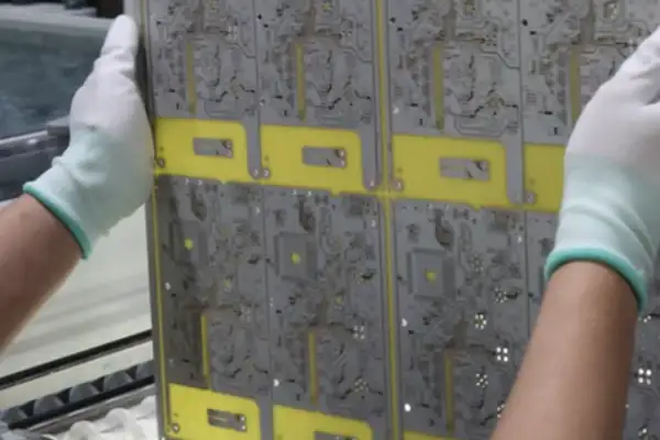
The most easily overlooked thing when building an electric-power-steering power board is actually copper thickness. I’ve seen too many design teams pour all their effort into control algorithms, then, at the PCB prototyping stage, casually find an ordinary board factory using 1oz copper and submit it — the result being the prototype overheats within a few minutes of running, even burning through the copper foil. An Electric Power Steering PCB is different from an ordinary motor-drive board — it has to continuously output several dozen amps of current in a space as narrow as a steering column, with extremely poor thermal-dissipation conditions. At this point, you must talk to people who’ve genuinely done Heavy Copper PCB manufacturing — they can give you a stack-up scheme with 4oz outer layer and 3oz inner layer, and know how to solve resin-fill and etch-uniformity problems for heavy-copper boards — details an ordinary board factory simply can’t handle well.
On MOSFET placement on this board, many people follow the reference design and line them up in a row, thinking symmetric routing is enough. Actually, once the six transistors’ arrangement stretches out, inductance on the high-current path quietly eats into your efficiency. I habitually pack the three half-bridges tightly together, with high-side and low-side transistors almost back to back, minimizing the power loop’s area. Then, I solder a capacitor directly next to each pair of transistors — not the bulky electrolytic kind, but a small-size X7R ceramic, placed right against the drain and source — this is far more useful than placing a pile of DC-link capacitors at the board edge. This approach doesn’t require calculating complex parasitic parameters — the key is physically making the loop as short as possible.
Many people ask me why, even with a large-package MOSFET, heat still can’t be suppressed. Looking at their board, copper thickness is sufficient, but vertical thermal conduction was never considered at all. Heavy-copper board’s benefit isn’t just current-carrying — it can also spread heat quickly from underneath the transistor, conducting it through a via array to a thermal aluminum substrate on the backside. The problem is, an ordinary Heavy Copper PCB manufacturer can’t combine high-density vias with heavy copper — either vias clog, or heavy copper delaminates — this process threshold is genuinely high. Among the few I’ve partnered with, factories that can stably build over 3.5oz copper thickness while guaranteeing 0.3mm via quality — you can count them on two hands.
There’s another point: capacitor and inductor selection in an EPS controller can’t just look at rated values. Vehicle grid transients are far worse than you’d imagine, especially in a 48V system, where a load dump can spike above 55V. If your chosen electrolytic capacitor’s voltage-withstand margin is only 1.1 times nominal, it’ll bulge within a few months. On the power input, I series a ferrite bead, followed by a group of low-ESR mixed capacitors, plus a few small-value NP0s — this way, both high-frequency noise and low-frequency ripple get caught. This combination looks costly, but compared to later reworking an entire batch of steering gears, spending these extra few dollars is genuinely worth it.
Ultimately, an EPS power board tests not a single technology, but overall understanding of manufacturing process, component characteristics, and electrical environment. You can’t judge a board problem-free just from a few waveforms in simulation software — you need to dig into the board factory to confirm every process step, especially heavy-copper lamination and drilling parameters. My habit now: for every new project, first send a test board to a Heavy Copper PCB manufacturer to run through the actual process, measure the real copper thickness and dielectric-layer thickness, then come back and adjust the layout. This clumsy method is actually more reliable than any simulation.
Why Sampling-Resistor Precision Matters More Than the Datasheet Suggests
While working on electric power steering, my level of obsession over current sampling far exceeded what most people would imagine. Many people think placing a sampling resistor in the circuit paired with an amplifier settles it — but that’s really not the case. Especially once the power board has already used heavy copper PCB — as copper thickness increases, the entire board’s thermal mass and current path change, and the resistor’s own temperature drift and parasitic inductance start contending with you. I’ve worked with quite a few heavy copper PCB manufacturers — some can control copper thickness very evenly, but very few care about how copper-foil edge roughness affects sampling precision, let alone proactively remind you how to route to avoid eddy-current effects in high-current regions.
On the sampling resistor — early on we used a few-milliohm alloy resistor, nominally high precision, but the moment high current hit, that pad’s solder-paste thickness and the PCB copper foil’s tiny resistance would shift the actual value. I later just measured it myself — running constant current through a few boards, using a multimeter to directly measure the voltage drop across the resistor, back-calculating the true resistance value — and found the nominal value and actual working value could differ by over ten percent — how could you expect FOC to calculate accurately with that? So in later design, I’d rather spend more space using two resistors in parallel per phase, distributing the current, and also lowering individual resistor heating — temperature drift’s effect on the sampling result becomes much smaller. But this brings another headache — if the parallel resistors’ layout is even slightly asymmetric, the two paths’ impedance becomes unbalanced, current distribution becomes uneven, and the sampled voltage signal carries an extra noise component — even more of a headache to handle.
Many people today think using a Hall sensor saves effort, avoiding the fight with copper foil. But the Hall’s own bandwidth and delay, in a system like EPS needing fast response, can sometimes be harder to serve than resistor sampling. I tried an open-loop Hall once — at the instant of motor stall, its output showed a noticeable overshoot — though lasting only tens of microseconds, that was already enough to make the controller misjudge, producing an unnecessary assist fluctuation. So I later went back to the resistor-sampling path, relying entirely on layout and component selection to power through. When selecting a heavy copper PCB manufacturer, I specifically pick ones that can provide copper-thickness cross-section reports, because copper-thickness consistency on the current-sampling path directly determines the sampling signal’s noise floor — you can’t rely on filtering forever to remove noise; once filter bandwidth comes down, phase-current real-time performance is gone — fatal for EPS. Current sampling was never a simple analog-quantity acquisition problem — it’s the starting point of the entire system’s response speed. For example, in FOC control, the current loop typically needs to run at an update rate of tens of kilohertz — every extra microsecond of sampling delay accumulates phase error in the current vector, directly compressing torque-control bandwidth. I ran a comparison — same motor, using a low-delay resistor-sampling scheme, the torque-buildup time from steering-wheel stationary to rapid steering input could be controlled under ten-some milliseconds, while switching to a Hall scheme with noticeable group delay stretched this time to several dozen milliseconds — the “responsiveness” feel in the driver’s hands immediately went numb. Moreover, the current-sampling noise floor also determines whether rotor-position information can be reliably extracted at low speed, small current — for sensorless FOC, this is often the key to whether startup succeeds. So during layout, even routing a few extra millimeters could introduce nanohenry-level parasitic inductance, generating ringing on the PWM edge, coupling into the sampling circuit, causing the ADC’s read value to jump — this kind of high-frequency noise is very hard to fully eliminate through software filtering — it can only be suppressed at the source. I also specifically ran a temperature test — from -40°C to 125°C, the same board’s sampling-resistor temperature-drift curve wasn’t linear, especially in the high-temperature range, where the copper foil’s resistance temperature coefficient adds in, and the entire sampling gain drifts an extra few percentage points. If online calibration isn’t done, FOC’s current-estimation error will vary with temperature, causing assist magnitude to be inconsistent between a cold and a warm vehicle — a genuinely maddening consistency problem in full-vehicle calibration. I later reserved a precision current-source calibration loop on every power board, automatically measuring actual gain and offset during power-on self-check, then writing to EEPROM — that’s what finally stabilized sampling precision within 1 percent across the full temperature range.
Why Torque-Sensor Signals Danced Along With the High-Current Traces
Working on the EPS controller, what genuinely gave me the biggest headache was never the algorithm — it was how to keep the torque signal on the board from dancing along with the high current. You’d test it fine in the lab, but the moment it’s installed in a vehicle and the motor runs, the sensor signal fills with glitches, steering-wheel feel turns gritty, and sometimes it even shudders on its own — like turning on a faucet and the water flow surges unpredictably. We later took it apart and found the problem was in the copper layout — using an ordinary PCB, ground-return handling wasn’t done well, and the six or seven-dozen amps of phase current wandering across the board directly swamped the torque sensor’s millivolt-level signal.
We switched to a factory doing Heavy Copper PCB manufacturing, pulling the power loop out onto a dedicated thick-copper layer, copper thickness pushed directly to 4oz, inner layers carrying high current, surface layer holding signal routing, ground plane cut cleanly — power ground and signal ground meeting at just one point at the battery negative terminal. This change alone completely transformed the board’s noise level. But don’t think that’s the end of it — the torque sensor’s two output signals, we insist on using independent conditioning chains, with even the power supply pulled from two independent LDOs on the SBC, sampled through different ADC channels, with real-time correlation checking done inside the MCU. Once the primary-secondary signal difference exceeds a calibrated threshold, the software immediately pulls assist away, switching to safe state — this redundancy isn’t creating trouble for ourselves — it’s a baseline.
Then there’s the position-sensor signal set — many peers think a magnetic encoder outputting ABZ or SENT can just be routed straight over. But actually, once the trace passes near the motor and power transistors, interference is enough to eat away pulse edges. I later mandated, on the Electric Power Steering PCB, that all position-sensor interfaces must use differential-pair routing, with a termination resistor at the end, and a hysteresis comparator at the receiver, and every board must pass surge and BCI testing before shipping ex-factory. Put plainly, none of this signal processing is that profound, but every single detail is exactly what keeps steering feel from becoming floaty, sticky, or losing control.
Why the Original Board’s Copper Trace Had Turned Yellow
A while back I helped a friend repair a steering system — his old car’s EPS would occasionally suddenly get heavy, with the fault code pointing to a torque-sensor signal anomaly. This problem was quite tedious to trace — we eventually found it wasn’t the sensor itself that was bad — it was that the signal line on the circuit board was being interfered with in disarray by an adjacent high-current copper trace. After swapping in a re-laid-out control board, the problem disappeared immediately. Signal lines in an EPS are too delicate — get slightly too close to the power loop and they act up.
I later curiously took apart the original-equipment board, and it looked to me like copper thickness was insufficient no matter how I looked at it. The high-current trace had turned yellow, with a ring of thermal-stress marks around the pads. This Electric Power Steering PCB has to carry several dozen amps of current every single day, while also guaranteeing that those signal traces less than a millimeter wide stay free of interference — the requirement placed on PCB manufacturing process is far harsher than an ordinary automotive board. So I started paying attention to factories specializing in heavy copper, and found that a genuinely reliable Heavy Copper PCB manufacturer isn’t simply about thickening the copper — they understand better how to work between the heavy-copper layer and the signal layer, solving both thermal and electromagnetic problems together. Some factories recommend using buried copper blocks or copper posts to conduct heat directly to the housing, while keeping the signal layer’s reference plane intact — this way, during routing, you don’t always have to worry about that signal line getting glitches from ground bounce.
Put plainly, the signal-line layout on an EPS control board tests not routing technique, but the manufacturer’s process ceiling. You can hand a small factory a Gerber file, and maybe electrical testing passes — but after a few months installed in a vehicle, once high temperature and heavy vibration hit, chronic issues like solder-joint microcracks and copper-foil peeling all emerge. When I later handle this kind of board, I only look for board factories with heavy-copper certification, and I always require them to provide local copper-thickness cross-section reports, especially at the high-current loop and the signal-ground split points. Once a signal is contaminated on the PCB, no amount of software filtering can save it — the end result is that instant your hands are on the steering wheel, the feel just isn’t right.
Why the Shutoff Path Failed Even When the Diagnostics Never Caught It
Building electric power steering boards, what gives me the biggest headache isn’t MCU model selection — it’s whether those few layers of copper foil can withstand instantaneous current impact. I followed a few projects early on that used conventional 2oz copper thickness — the result was that during stall testing, the PCB’s temperature rise spiked to unacceptable levels. We later honestly found a factory specializing in heavy-copper PCBs, going straight to 4oz or even 6oz, and only then suppressed the heat generation in the three-phase bridge section. Many people think this is purely a manufacturing-process issue, but it completely determines whether your shutoff path can work at critical moments.
If the power loop on an Electric Power Steering PCB isn’t handled well, however powerful your MCU’s fault-detection mechanism, it’s worthless. I’ve seen designs that made the MCU’s safety-shutoff logic extremely complex — an independent monitoring chip, hardware interlocks — but PCB traces, at the vias, due to insufficient current-carrying capability, developed microcracks after long-term thermal expansion and contraction, causing a certain MOSFET’s gate-drive signal to intermittently break — this kind of failure mode couldn’t even be caught by the main MCU’s diagnostics — it only surfaced by chance when steering-torque fluctuation was noticed during road testing. So later, I’d rather spend more cost on board-level design, laying the drive and power loops directly with heavy copper, lowering the entire power loop’s parasitic inductance, saving the trouble of adding a pile of compensation circuits later.
The safe state of a three-phase motor is dizzying enough on its own. The braking torque generated by active short circuit might not matter much at low speed, but at high speed, suddenly giving the rear wheels a reverse torque is no joke. In one scheme I participated in, to save on external independent shutoff logic, we let the MCU’s internal hardware fault-collection unit directly trigger three-phase open circuit — but the problem was, if the MCU’s own power rail collapsed first, the entire shutoff chain would fail. So even with the MCU’s internal lockstep core and memory ECC, we still added an extra, fully independent hardware shutoff path, pulled directly from the SBC to the pre-driver’s enable pin, implemented purely with combinational logic, making no judgment dependent on MCU state at all. This path’s PCB routing also used a dedicated heavy-copper layer, separated from the signal layer, preventing crosstalk.
Finding a heavy-copper board factory isn’t as hard as it was a few years ago — many factories can now build 6-layer-plus buried/blind-via heavy-copper boards. But the key is getting them to understand your design intent. I generally directly explain to the manufacturer which nets carry sustained high current and which are transient pulses — uneven copper thickness causes board warpage, hurting placement yield. And the solder-mask opening area on the shutoff path needs to be carefully calculated, or uncontrolled solder-paste amount is equivalent to artificially adding an uncertain resistance on a critical path. None of these details are written in a textbook — they’re all learned by stepping into pits on real projects. For example, once, to further lower the power loop’s resistance, we increased copper thickness to 8oz — the result was that the board’s warpage severely exceeded spec, and the pick-and-place nozzle couldn’t hold it during SMT, with reject rate climbing steeply. We only learned, after repeated back-and-forth with the manufacturer, that a heavy-copper board’s inner-layer copper distribution must be symmetric, or lamination stress becomes uneven — even if you balance copper in the design, actual post-etch residual-copper-area differences still cause warpage. We ended up having to slightly thin the top and bottom layer copper thickness while adding dummy copper regions to balance stress — that’s what finally pulled yield back up. Also, for the solder-mask openings on the shutoff path, I generally require the manufacturer to build a stepped stencil, ensuring solder-paste amount is precisely controllable, because if there’s too much solder paste, the resulting solder-joint height after reflow becomes inconsistent, easily causing stress concentration in a vibration environment, actually reducing reliability. At the DV testing stage, we specifically ran loaded thermal cycling — from -40°C to 125°C, 500 continuous cycles — using thermal imaging to observe the power loop’s temperature rise, finding that if copper thickness near vias was insufficient, hot spots would be extremely concentrated, and over the long term, the CTE difference between copper foil and substrate would cause hole-wall fracture. So afterward we mandated that all high-current vias must have plated fill, and via count must be doubled, using a parallel scheme to distribute current — this way, even if individual vias fail, the overall loop can still maintain low impedance. This kind of redundant design looks like it adds cost, but compared to the risk brought by a steering-system failure, it’s entirely worth it.
Working in automotive electronics, especially EPS, I increasingly feel that choosing the right reliable heavy-copper PCB manufacturer matters more than piling on any number of technical parameters. I used to always fixate on routing and component placement, thinking that as long as the design was solid, a slight shortfall in process could still be adjusted back. Later, getting burned on a few projects, I understood it’s not that simple. The high-current path on an Electric Power Steering PCB routinely sees pulses of several dozen amps — copper thickness is nominally 3oz, but actually built, some places don’t even reach 2.5oz — how is the gate-drive loop supposed to stay stable? That’s simply not something you can fix by tuning a resistor. So now, when I talk with engineers around me, I always say one thing: don’t save that little bit of money on the board factory — find a genuine heavy-copper expert who understands automotive high-current boards. Copper-thickness uniformity, bond strength between copper foil and substrate, via-fill quality — these are the foundation of whether your power system can withstand transient shock.
Why Total Physical Isolation for the SBC Backfired
Many people, discussing the SBC’s independent power supply, jump straight into emphasizing “physical isolation” and “redundant power domains,” as if not completely separating them makes it unsafe. I actually think excessively pursuing independence can easily create pitfalls for yourself. For example, connecting the SBC directly to the battery, and pulling a separate LDO or tracker to power the sensor, sounds perfect on paper — but in actual conditions like a vehicle’s low-voltage droop or cold-start pulse, a strange competition arises between the SBC’s back-end capacitor energy storage and the main DC-DC’s residual energy — once startup timing gets disordered, the entire system could actually lock up in an unknown state. I prefer to understand the SBC’s power supply as “limited independence” — it can take power directly from the battery, but its power-down timing and monitoring logic must have a clear handshake relationship with the main DC-DC’s power domain. I even allow the SBC, in certain low-power modes, to briefly borrow energy from the main domain to maintain state logging, rather than losing memory entirely the instant power drops. This looks like it breaks independence, but the system’s overall robustness is actually higher.
On the gate side, heavy-copper PCB’s value becomes even more obvious. Many people agonize over what resistance value to use for the gate resistor, slowing turn-on/turn-off to lower radiation — but if your board’s copper isn’t thick or wide enough, loop parasitic inductance is large, and no matter how many RC snubbers you parallel, you can’t suppress the ringing. I saw a case where the board used conventional 2oz copper, and the gate trace wound around a bit to avoid other signals — the result was the MOSFET’s shutoff spike shot directly to 1.5 times rated voltage. It was ultimately solved not by tuning the gate resistor, but by switching to a manufacturer capable of embedding heavy-copper blocks, laying the entire power loop with 6oz copper foil — that’s what suppressed the ringing. So don’t always look for answers in the component — sometimes your PCB itself is the biggest interference source, and also the best filter. These power-supply-level details are all hidden in the thickness and purity of the copper.
Ultimately, EPS hardware design, talked through to the end, is about matching reliability with manufacturing capability. However smart the SBC, however fast the logic gates, if you give it a PCB with uneven copper thickness and poor mid-layer thermal dissipation, it’ll still fail under high temperature and vibration. When selecting a board factory now, I always ask two questions: can you guarantee the heavy-copper region’s copper foil won’t peel after thermal cycling, and have you run 1000-hour power-cycling aging validation? These give me more peace of mind than any curve on a datasheet.
Why the Solder Joint That Failed Wasn’t Even in the Power Section
Looking back over years of automotive-electronics hardware design, the board for the electric power steering system is definitely one of the things people love and hate at the same time. Many people discussing EPS like to focus attention on control algorithms or torque-sensor precision, but often overlook a more fundamental fact: all those clever strategies ultimately have to be executed by a palm-sized circuit board, and this board’s physical performance often determines whether the entire system survives the first three years.
For a while, I dealt with Heavy Copper PCB manufacturers almost every day, because conventional-process power sections simply couldn’t hold up — running durability testing on the bench, halfway through, we’d find the copper foil in the MOSFET region visibly discoloring, even blistering. We later cross-sectioned it for analysis and understood that simply increasing copper thickness wasn’t enough — you need to consider the thermal-conduction path between different copper layers, and the resin system’s degradation speed under repeated thermal shock. We eventually pulled the power loop’s copper thickness above 4oz, and required the supplier to use high-Tg, low-CTE substrate material — that’s what barely suppressed the stress problem caused by junction-temperature fluctuation. This process taught me deeply how critical it is to find a manufacturer genuinely capable of true heavy-copper boards. Plenty of factories in the market claim they can do it, but ones that can properly match heavy copper with fine-pitch circuitry while also guaranteeing interlayer bond strength — there are only a handful.
There’s another thing especially easy to underestimate: the connector. It’s not that people don’t take part selection seriously — it’s that many don’t realize the high-current interface on an EPS module is both an electrical channel and the most concentrated point of mechanical stress. Once, during winter road testing, a vehicle ran less than 200 kilometers continuously on a bumpy road and reported a steering-assist fault. Investigating, we found the power connector’s solder joint had developed a microcrack — invisible to the naked eye, only catchable with X-ray. Reviewing it afterward, we found this was because, during PCB layout, we’d placed that heavy connector near the board edge without extra reinforcement of its mounting legs — relying solely on the pads to hold it. Over long-term vibration, the solder joint became the weak link. Since then, my habit is: whenever a connector involves high current or frequent vibration, I always do secondary structural fixation — either screw-locked, or using a metal bracket to redirect stress to the housing — never letting the solder joint bear mechanical load alone.
EMC is an especially notorious problem area for EPS. Those thick motor phase-line cables are themselves a strong radiation source, especially during PWM modulation, where the spectrum can be absurdly wide. One project I remember vividly — during early EMC investigation, BCI testing kept stalling at a specific frequency band, with CAN communication dropping frames badly. After a long investigation, we found the problem was in the torque-sensor signal loop — that wiring harness ran from the steering column all the way to the ECU, and though shielded cable was used, handling at the module entry point was too casual — the shield layer was just a few wires twisted together and soldered to a ground hole, never forming a complete low-impedance loop. We later switched to a 360-degree circumferential connection, specifically designing a bonding structure from the connector housing to the chassis ground — the problem improved considerably right away. This also made me realize that for these sensitive small-signal channels, common-mode chokes and differential-mode filtering aren’t optional — they’re mandatory, and must be laid out right next to the connector pins during layout, or those extra few millimeters of trace could become an efficient pickup antenna.
Ultimately, a reliable Electric Power Steering PCB is never something you settle by translating a schematic into layout and casually finding a factory to prototype. It requires you to blend thermal-gradient distribution, mechanical resonance frequency, and current-return path together and repeatedly deliberate right from the design start. Cost pressure often forces you into compromises — like drilling fewer ground holes or switching to cheaper board material — but these compromises eventually get paid back doubled in some road test or customer complaint. I now actually think spending more time upfront communicating clearly with a Heavy Copper PCB manufacturer about process boundaries, even having them get involved early in stack-up design, is the real shortcut to saving money. After all, the cost of patching things up afterward is always far greater than the cost of getting it right the first time.
Why a Fastener Weighing More Than 5 Grams Needs Silicone Reinforcement
In electric-power-steering hardware design, what I fear most isn’t a complex schematic — it’s always assuming it’ll work fine in principle, only to have something go wrong the moment it’s installed in a vehicle. What left the deepest impression: a board had already passed bench testing, was installed and running road tests, and then suddenly showed steering-assist fluctuation on a bumpy road. We investigated for two weeks, capturing every signal we could think of, and finally found that an electrolytic capacitor’s pin on the power board had developed an invisible microcrack under vibration — the pad wasn’t damaged; it was metal fatigue in the capacitor body’s own pin. After that, we set an iron rule: any through-hole component weighing over 5 grams, regardless of what the datasheet says, must be reinforced with silicone, and the adhesive must cover the entire ring where the component body contacts the PCB — not just a single dot.
Very often, the power board’s problem isn’t insufficient current — it’s heat and mechanical stress that kill you. We used to always calculate current-carrying capacity — so many ounces of copper thickness, so much temperature rise — and once we thought it was enough, we’d finalize the design. We later found the genuinely fatal thing wasn’t sustained current at all — it was the tens-of-milliseconds stall condition, where current surges to three or four times rated value — copper foil heats instantly, and its thermal-expansion coefficient differs from FR4 — go through this a few times, and the inner-layer copper starts curling up. This is also why I later specifically screen manufacturers — for this kind of heavy-copper PCB, you must find someone who genuinely understands heavy-copper PCB manufacturing — not a factory that only thickens the outer copper while keeping the inner layers at standard process. Some manufacturers claim they can do 4oz, 6oz, but inner-layer copper thickness is uneven, and resin fill during lamination is poor — the moment high current hits, hot spots form — and what ultimately burns through isn’t the trace — it’s the via. A Heavy Copper PCB manufacturer we later partnered with had a crude but effective method: passivating the inner-layer copper’s edges and corners before lamination, avoiding tip discharge, while using high-Tg polyimide material that resists delamination at high temperature. Nobody tells you this kind of detail without going through a few rounds of rework.
We got burned badly on connectors too. We used to think spring terminals were reliable enough — plug in, hear a click, locked tight. The result: after running through the frequency spectrum on the vibration table, contact resistance jumped from 0.5 milliohms to over ten milliohms, completely randomly. Analysis showed it was fretting wear — the plating had worn through, and bare copper had oxidized directly. So now, all connectors on the EPS that carry high current or critical signals must have a secondary locking mechanism, and the terminal itself must be a dual-contact structure. More critically, the connector’s soldering to the PCB can’t rely solely on a few surface-mount pads — it needs through-hole reflow or press-fit, transmitting mechanical stress to the other side of the board. Surface-mount solder joints can handle tension okay, but their shear resistance is genuinely fragile — twist it and it cracks.
The MCU-and-SBC shutoff path is another easily overlooked dark corner. Functional-safety requirements always say that if the MCU crashes, the SBC should be able to independently shut off the three-phase bridge. But in actual circuits, the SBC’s shutoff signal needs to pass through a logic gate or level shifter before reaching the pre-driver — many people, to save effort, hang this conversion chip’s power on the MCU’s I/O power rail. The moment the MCU resets, that power rail might get dragged down, the conversion chip loses power along with it, and the shutoff signal can’t get through — the bridge is still conducting, and the motor spins wildly. We ran fault-injection testing — the lockstep core reported an error, the MCU reset, the SBC’s ERR pin pulled low — but the motor still spun for about 200 more milliseconds — enough to push a vehicle off a lane. We later hung that level-shifter’s power independently onto the SBC’s safety power output, completely separating it from the MCU’s power — that’s what finally settled it. This made me realize: whatever “independent shutoff path” you have, if power, clock, or reference shares even one common source, independence is a joke.
Torque-sensor ground handling also came with plenty of hard lessons. We used to always think separating analog ground and power ground, then connecting them at one point at the end, was enough — the result was still noticeable glitches on the sensor signal. Investigating, we found that “single-point connection” trace actually wound around a long path on the PCB, and shared a segment of copper foil with power ground. We later pulled the sensor signal ground, supply ground, and ADC reference ground out independently, connecting directly to an independent LDO’s ground pin, with that trace length under 15mm, surrounded entirely by shielding ground — the current loop never touched the power region at all. Put plainly, you have to treat the sensor ground like a precision signal line — don’t treat it as a ground line, or noise will teach you a lesson.
Why the Real Test Isn’t Any Single Component but the Physical Details Together
I’ve worked with quite a few teams building steering systems, and what gives them the biggest headache is often not the control algorithm — it’s that board carrying high current and signal lines. The Electric Power Steering PCB’s role in a vehicle is especially special — it has to instantaneously output several dozen amps to drive the motor, while also guaranteeing the angle sensor’s signal stays perfectly clean, with zero interference tolerated. If this kind of board is handed to an ordinary PCB factory, it’ll mostly run into problems on thermal and lifespan testing — the key is copper thickness. Ordinary 1oz copper foil simply can’t withstand sustained high current — once temperature rise climbs, not only does efficiency drop, but the entire system’s thermal protection kicks in prematurely too — that’s a genuinely terrible experience.
I later talked in depth with several Heavy Copper PCB manufacturers and only then realized that heavy-copper process isn’t simply thickening the copper. Once copper-foil thickness exceeds 3oz, etch precision, layer-to-layer registration, and solder-mask fill all become especially tricky. Even more troublesome, steering systems have extremely high requirements for vibration and thermal-cycling resistance — if copper is too thick, CTE-mismatch stress concentrates at the vias, and over time, microcracks appear — this is fatal. So the genuinely knowledgeable manufacturers do extra handling on via protection — like resin plug or cap plating — to disperse the stress, rather than just doing a simple tenting.
The concept of safety in a steering system can’t rely on software redundancy alone. I’ve seen designs where dual MCUs cross-validate each other, looking quite comprehensive, but both signals ultimately converge onto the same PCB — if the power layer shorts here, all redundancy instantly fails. So genuine redundancy must start at the physical layer — PCB design must isolate two independent power networks, even routing power through different inner-layer copper in a multilayer board, strictly separated by dielectric in between, with ground plane also split, avoiding common-cause failure. Many designers initially think this is unnecessary, too expensive, taking too much space — but once something goes wrong, there’s no chance for regret.
Once, testing a sample, we found a glitch always appeared on the sensor signal when motor current changed abruptly. We investigated for a long time and finally found it was ground bounce formed by high current in the power loop on the PCB, coupling through common ground impedance into the sensitive circuit. We later changed the layout, making power ground and signal ground a single-point star connection, and laying the high-current routing area as a dedicated wide copper block with heavy copper, reducing loop inductance — that’s what solved the problem. This experience taught me that automotive-grade things aren’t sometimes about how complex the principle is — it’s about control over every physical detail — not one bit can be off.
Many people today think a PCB is just a hardware carrier, putting all their attention on the chip and algorithm — this is actually quite dangerous. Electric power steering is a product concerning personal safety — every PCB in it is a miniature safety regulation, from copper-foil thickness to via position, all part of the failure-mode picture. To build a system people can trust, you must treat the PCB as a complete safety component, not simply a connecting board.
What actually makes a long-term PCB supply chain partnership work — shared
Practical, experience-based strategies for how to reduce PCB procurement risks — from
Real factory-floor lessons on how to optimize a PCB manufacturing process —
• Expert in Small-to-Medium Batch Production
• High-Precision PCB Fabrication & Automated Assembly
• Reliable Partner for OEM/ODM Electronic Projects
Business Hours: (Mon-Sat) From 9:00 To 18:30
Get quote, solution or any question, Andre always here to help